Table of Contents
Advertisement
Advertisement
Table of Contents

Related Manuals for Oerlikon Torque-Hub CW18 Series


Summary of Contents for Oerlikon Torque-Hub CW18 Series
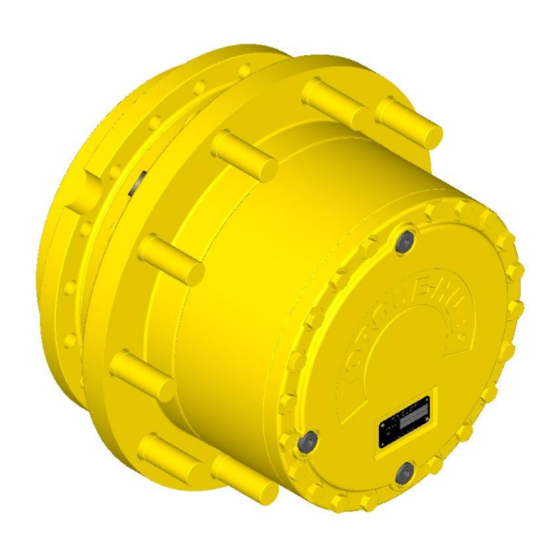
- Page 1 ® Torque-Hub Planetary Final Drive CW18 Series Service Manual Rev 01/28/14...
- Page 2 While every precaution has been taken in the preparation of this document, Fairfield Manufacturing Co. Inc. assumes no liability with respect to the use of the documentation described herein, or for any act or omission of Fairfield Manufacturing ® Co. Inc. concerning this documentation. Torque-Hub is a registered trademark of Fairfield Manufacturing Co.
-
Page 3: Table Of Contents
Planetary Final Drive Service Manual Content Introduction Brake Test Roll and Leak Test Tightening and Torquing Bolts Lubrication Information Seal Installation Instructions Disassembly Instructions Main Disassembly Cover Disassembly Input Coupling Disassembly Input Brake Disassembly Housing-Spindle Disassembly Output Planet Gear Disassembly Input Carrier Disassembly Assembly Instructions Cover Subassembly... -
Page 4: Introduction
Planetary Final Drive Service Manual Introduction This manual is a step-by-step guide to the disassembly and ® assembly of the CW18 Torque-Hub units with ratios of 51:1 or lower. It is designed for the customer or mechanic who is repairing ®... -
Page 5: Brake Test
Planetary Final Drive Service Manual Brake Test The Brake Test To perform a brake check, use a M12x1.5 metric fitting. Install a hydraulic hand pump with pressure gauge into brake port in spindle (1A) using metric thread fitting. Place ROLL TEST Tool (refer to table on page 8) into input coupling. - Page 6 BRAKE CHART DIGIT FULL BRAKE NUMBER RELEASE RELEASE MAXIMUM BRAKE MODEL RELEASE PART PRESSURE PRESSURE PRESSURE TORQUE CODE PRESSURE NUMBER SPRINGS MIN (psi) MAX (psi) (psi) (in-lbs) (INPUT (psi) BRAKE) AM902446A 3000 3754 AM902446B 3000 5411 AM902446C 3000 6386 AM902446G 3000 4422 AM902446A...
- Page 7 ARE SUBJECT TO SPRING PRESSURE. MAKE SURE THE RETAINING RING IS SECURED BEFORE REMOVING BOLTS. Re-test the input brake. If release and/or lockup pressures still do not match the brake chart, contact the Oerlikon Fairfield service department. BRAKE LEAK REPAIR PROCEDURE: Install input brake bolts into holes in the Brake Piston.
-
Page 8: Roll And Leak Test
Planetary Final Drive Service Manual Roll and Leak Test ® Torque-Hub units should always be roll and leak tested before disassembly (if possible) and after assembly to make sure the unit’s gears, bearings and seals are working properly. The following information briefly outlines what to look for when performing these tests. - Page 9 Model Code Roll Test Tool CW18Ex1xxx T184729 CW18Ex2xxx T180149 CW18Ex4xxx T180149 CW18Ex7xxx T201476 CW18Ex8xxx T205279 The Leak Test The purpose of a leak test is to make sure the unit is airtight. To perform a leak test, use the leak test fixture from the table on page 10.
- Page 10 Model Code Leak Test Tool CW18A11xxAxxx T182969 CW18A11xxZxxx T188489 CW18D11xxAxxx T188489 CW18D12xx4xxx T181663 CW18D14xxBxxx T184035 CW18D18xx4xxx T198122 CW18D21xxAxxx T188489 CW18E11xxAxxx T188489 CW18E11xx4xxx T188489 CW18E12xx4xxx T181663 CW18E14xxBxxx T184035 CW18E17xx8xxx T163056 CW18E18xx4xxx T198122 CW18E54xxBxxx T184035...
-
Page 11: Tightening And Torquing Bolts
Planetary Final Drive Service Manual Tightening and Torquing Bolts If an air impact wrench is used to tighten bolts, extreme care should be taken to ensure the bolts are not tightened beyond their specified torque. The following steps describe how to tighten and torque bolts or socket head cap screws in a bolt circle. -
Page 12: Lubrication Information
95 cst and maintain a minimum viscosity of 40 cst under normal operating conditions. Some applications require special considerations; consult the machine manufacturer and Oerlikon Fairfield for more additional information. The table below lists the recommended viscosities for various ambient operating temperatures. These recommendations are based on temperature rise of 50°... - Page 13 Oil temperatures should be not higher than 160° to 180°F for continuous operation, and no higher than 200°F for intermittent operation. For special applications, high horsepower, high speeds or wide temperature changes, please consult Oerlikon Fairfield. ® Oil Fill Level...
-
Page 14: Seal Installation Instructions
Planetary Final Drive Service Manual Seal Installation The seal installation tool can be purchased from MORCOR LTD at Sales@MORCORLTD.com part number MGT045. To begin the procedure, all of the sealing components; Seal Rings (metal rings); O-Rings and the housings must be clean and free of Oil, Grease, Dirt or Dust. - Page 15 With all surfaces of the O Ring (2) wet with alcohol use the Installation Tool (9) to position the Seal Ring (1) and the O-Ring (2) squarely against the Housing (5) as shown. Use sudden and even pressure to pop (push) the Toric Ring under the Retaining Lip (3) of the housing.
- Page 16 After a successful installation always wait a few minutes for the Alcohol to completely evaporate, before assembling. The Alcohol is necessary as a lubricant during the installation process, but for assembly the area must be clean and dry in order for the O- Ring to properly "crush"...
- Page 17 DISASSEMBLY...
-
Page 18: Main Disassembly
Planetary Final Drive Service Manual Main Disassembly Continued on Next Page... - Page 19 Perform a roll check and a leak check prior to disassembling the unit. Remove the three magnetic Pipe Plugs (1U/14) and drain the oil out of the gearbox. NOTE: Record the condition and volume of the oil. Remove Bolts (27/13) from the Cover Subassembly. Lift the Cover Subassembly off of the unit.
- Page 20 Remove the Input Shaft (7) if applicable. Lift out the Input Carrier Subassembly from Hub-Spindle Subassembly. Remove the Second Stage Sun Gear (12). Lift the Ring Gear (4/6) off of the Housing Spindle Subassembly. Remove the O-ring (5) from between the Housing (1G) and the Ring Gear (4/6). CAUTION: Safety glasses must be worn during these next steps.
- Page 21 Remove Adaptor Mount (24) from Housing Spindle Subassembly by uninstalling Bolts (26). NOTE: Skip step 14, if Thrust Washer (30) is glued onto Adaptor Mount (24) Remove Thrust Washer (30) from Adaptor Mount (24). Remove O-Ring (25) from groove in Adaptor Mount (24) and discard O-Ring. Remove the Input Brake Subassembly out of Hub-Spindle Subassembly (Refer page 26 for Input Brake Disassembly).
-
Page 22: Cover Disassembly
Planetary Final Drive Service Manual Cover Disassembly Continued on Next Page... - Page 23 Remove the O-Ring (5) from groove in the Cover (6A/12) and discard O-Ring. NOTE: Skip step below if the unit has Thrust Washers glued in place. Remove Thrust Washers (10) and (11) from pockets in the Cover (6A/12). This concludes the Cover Disassembly.
-
Page 24: Input Coupling Disassembly
Planetary Final Drive Service Manual Input Coupling Disassembly Continued on Next Page... - Page 25 CAUTION: Safety glasses must be worn during these next step. Remove Retaining Ring (22/18C) from bore of Coupling (9/18A). NOTE: Skip step 2 for Assembly with Adaptor Mount. Remove Retaining Ring (18B) from retaining ring groove of Coupling (9/18A). This concludes the Input Coupling Disassembly.
-
Page 26: Input Brake Disassembly
Planetary Final Drive Service Manual Input Brake Disassembly Continued on Next Page... - Page 27 Remove Input Coupling Subassembly from the unit. Place Spindle (1A) such that the flange side is up. CAUTION: Safety glasses must be worn during these next steps. Install the Input Brake Bolts through the Thrust Plate (18B) and into the Brake Piston (18A) and tighten incrementally to compress the brake springs (18R) and take pressure off of the Retaining Ring (18E).
-
Page 28: Housing-Spindle Disassembly
Planetary Final Drive Service Manual Housing-Spindle Disassembly Continued on Next Page... - Page 29 Set the unit on a bench so that the Spindle (1A) flange is down. Continued on Next Page...
- Page 30 Using a small drill bit (typically 1/8”), drill from the top of the bearing nut to the bottom as shown below. Using a larger drill bit (typically 5/16”), drill the bearing nut from the shoulder of the bearing nut to the bottom as shown below. Using a chisel, split open the bearing nut through the larger drilled bore as shown below.
- Page 31 Remove Bearing Nut (1E) out of Hub-Spindle Subassembly. Discard Bearing Nut (1E). A new locknut must be used for reassembly. Turn the unit over and carefully place the unit on a support base until the Spindle (1A) rests on it. Ensure there is enough gap to lower the Housing (1G) down. Use a dead blow hammer on the Housing (1G) flange to drive the inboard Bearing Cone (1F) off of the Spindle.
-
Page 32: Output Planet Gear Disassembly
Planetary Final Drive Service Manual Output Planet Gear Disassembly Place the Planet Gear Sub Assembly on bench. CAUTION: Safety glasses must be worn during this next steps. Remove the upper Retaining Ring (3D) from groove of the Planet Gear (3A). Remover Spacer Rings from either side of the Roller Bearing Assembly (3B). -
Page 33: Input Carrier Disassembly
Planetary Final Drive Service Manual Input Carrier Disassembly Drive the Planet Shaft (8D) out of the Carrier (8A) pin holes; forcing the Roll Pin (8E) to sheer off. Hold on to the Planet Gear (8F) and push the Planet Shaft (8D) out of the Carrier (8A). The Thrust Washers (8B) will slide off the shaft as it is removed. - Page 34 THIS PAGE INTENTIONALLY LEFT BLANK...
- Page 35 ASSEMBLY...
-
Page 36: Cover Subassembly
Planetary Final Drive Service Manual Cover Subassembly Continued on Next Page... - Page 37 Install three Pipe Plugs (1U/14) into the Cover (6A/12). Grease the O-ring (5) and place it in the groove in the Cover (6A/12). NOTE: Skip step below if the unit has Thrust Washers glued in place. Place the Thrust Washers (10) and (11) into counter bore of Cover (6A/12) using grease to hold it in place.
-
Page 38: Input Carrier Subassembly
Planetary Final Drive Service Manual Input Carrier Subassembly Apply a liberal coat of grease to the bore of the Planet Gear (8F). This will enable the Needle Rollers (8C) to be held in place during assembly. Install Needle Rollers (8C) into the bore of each of the three Planet Gears (8F). NOTE: The last roller installed must be installed end wise. - Page 39 Finish pushing the Planet Shaft (8D) into the Carrier (8A) until roll pin holes of Planet Shaft and Carrier are aligned. If necessary, align roll pin holes using a 1/8” diameter punch. NOTE: The chamfer on the Roll Pin hole should be towards the roll pin hole in the Carrier. Drive the Roll Pin (8E) into the roll pin hole in carrier and into the Planet Shaft (8D) until the end of the roll pin is flush with the outside diameter of Carrier (8A).
-
Page 40: Output Planet Gear Subassembly
Planetary Final Drive Service Manual Output Planet Gear Subassembly Apply a liberal coat of grease to the bore of the Planet Gear (3A). CAUTION: Safety glasses must be worn during this next steps. Install the upper Retaining Ring (3D) from groove of the Planet Gear (3A). Install the Roller Bearing assembly (3B) carefully. -
Page 41: Input Coupling Subassembly
Planetary Final Drive Service Manual Input Coupling Subassembly Continued on Next Page... - Page 42 CAUTION: Safety glasses must be worn during these next steps. Install the Retaining Ring (22/18C) into Coupling (9/18A). NOTE: Skip steps 2 and 3 for Assembly with Mount Adaptor. Install the Retaining Ring (18B) from retaining ring groove of Coupling (9/18A). This concludes the Input Coupling Subassembly.
-
Page 43: Housing-Spindle Subassembly
Final Drive Service Manual Housing - Spindle Subassembly Continued on Next Page... - Page 44 Using alcohol and a clean rag, wipe off bearing locations on the Housing (1G) and the Spindle (1A). Press one Bearing Cup (1E) into bearing counter bore of spindle end of housing until seated against shoulder in housing. Use Tool T179926/T176834. Turn Housing (1G) and press one Bearing Cup (1C/1E) using Tool T179926/T176834 into bearing counter bore of cover end of Housing (1G) making sure that it is fully seated against shoulder in the housing.
- Page 45 Place other Bearing Cone (1C) onto Spindle (1A) until it is seated in Bearing Cup (1C) in Housing (1G) and spray with a light coat of oil. If necessary, use Tool T176703 to press Bearing Cone (1C) onto Spindle (1A). Install Bearing Nut (1E) onto Spindle (1A) and tighten using locknut wrench T176285.
-
Page 46: Main Assembly
Planetary Final Drive Service Manual Main Assembly Continued on Next Page... - Page 47 Place Hub-Spindle Subassembly, spindle flange end down. Preheat bearing heating oven to 250°F. Install Thrust Spacer (2) into counter bore of Spindle (1A). Once oven has reached 250°F, place Planet Gear Sets (3A) into oven and leave in for 15 to 20 minutes.
- Page 48 Continued on Next Page...
- Page 49 NOTE: Use an air gun to clean up the brake port and make sure there are no chips inside. Place unit on bench such that Spindle (1A) flange side is up. Insert Coupling Sub-Assembly into Spindle (1A) bore and onto Input Shaft (7). Install Spacer (18J) into brake bore of the Hub-Spindle Assembly, applicable only for Splined Brake assembly Starting with a Stator (18C), alternately stack and install Stators (18C) into Lobes or Splines...
- Page 50 NOTE: Skip steps 29, 30 and 31 if unit does not have Adaptor Mounting (24). Grease and Install O-Ring (25) onto O-Ring groove of Adaptor Mount (24). NOTE: Skip step 30, if Thrust Washer (30) is glued onto Adaptor Mount (24) Install Thrust Washer (30) onto Adaptor Mount (24).
-
Page 51: Assembly Drawing
Planetary Final Drive Service Manual Assembly Drawing... -
Page 52: Parts List
Planetary Final Drive Repair Instructions Parts List Number Description SPINDLE FACE SEAL BEARING CUP/ BEARING CONE BEARING NUT HOUSING STUDS 1U/14 PIPE PLUG THRUST SPACER PLANET GEAR CYLINDRICAL ROLLER BEARING EXTERNAL RETAINING RING INTERNAL RETAINING RING RING GEAR O-RING COVER SUB-ASSEMBLY 6A/12 COVER PLATE INPUT SHAFT... - Page 53 Number Description INTERNAL RETAINING RING O-RING O-RING BACKUP RING BACKUP RING SPACER SPRING PLASTIC PLUG EXTERNAL RETAINING RING RETAINING RING ADAPTOR MOUNT O-RING DRIVE SCREW 27/13 BOLT THRUST WASHER NOTE: * For Spring (18R) quantity, refer to the Brake Chart under Brake Test on page 6.
-
Page 54: Assembly Tools
Planetary Final Drive Repair Instructions Assembly Tools T163056– ROLL CHECKING FIXTURE... - Page 55 T180149 – LEAK TEST ADAPTER...
- Page 56 T184729 – LEAK TEST ADAPTER...
- Page 57 T182969 – ROLL CHECK TOOL...
- Page 58 T198122 – BRAKE ASSEMBLY CONCENTRICITY...
- Page 59 T201476 – LEAK TEST ADAPTER PLATE...
- Page 60 T176834 – ASSEMBLY PRESSING TOOL...
- Page 61 T176703 – BEARING CONE PRESSING TOOL...
- Page 62 T176285 – ASSEMBLY LOCKNUT WRENCH...
- Page 63 T174699 – ASSEMBLY PRESSING TOOL...
- Page 64 T219294 – SEAL PRESSING TOOL...
- Page 65 T214917 – SEAL PRESSING TOOL...
- Page 66 T181663 – BRAKE ASSEMBLY CONCENTRICITY FIXTURE...
- Page 67 T184035 – BRAKE ASSEMBLY CONCENTRICITY FIXTURE...
- Page 68 T188489 – BRAKE ASSEMBLY CONCENTRICITY FIXTURE...
- Page 69 T205279 – LEAK TEST ADAPTER PLATE...
- Page 70 T179926 – ASSEMBLY PRESSING TOOL...
-
Page 71: Contact Information
Fairfield Manufacturing Co. Inc. U.S. 52 South / P.O. Box 7940 Lafayette IN 47903-7940 Shipping Address 2309 Concord Road Lafayette, IN 47909 Main (765) 772-4001 Applications Engineering (765) 772-4011 Sales and Service (765) 772-4010 E-mail Applications Engineering apps@fairfieldmfg.com Sales sales@fairfieldmfg.com Website www.oerlikon.com/fairfield... - Page 72 Oerlikon Fairfield U.S. 52 South / P.O. Box 7940 Lafayette, IN 47903 USA 765-772-4000 www.oerlikon.com/fairfield...
Need help?
Do you have a question about the Torque-Hub CW18 Series and is the answer not in the manual?
Questions and answers