Table of Contents
Advertisement
REPAIR MANUAL
SELF PROPELLED LIFT
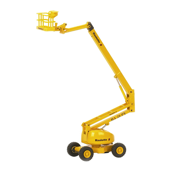
HA20 PX - HA26PX
242 031 9530 - E 02.03
GB
I S O 9 0 0 1
ARTICULEES
MATS
TELESCOPIQUES
CISEAUX
TRACTEES
L ' A C C E S
A
L ' E S P A C E
PINGUELY HAULOTTE • LA PERONNIERE - BP 9 - 42152 L'HORME • Tél. +33 (0) 4 77 29 24 24 • Fax SAV +33 (0) 4 77 31 28 11
email haulotte@haulotte.com • Web www.haulotte.com
Advertisement
Table of Contents

Related Manuals for Pinguely-Haulotte HA20PX

Summary of Contents for Pinguely-Haulotte HA20PX
- Page 1 REPAIR MANUAL SELF PROPELLED LIFT HA20 PX - HA26PX 242 031 9530 - E 02.03 I S O 9 0 0 1 ARTICULEES MATS TELESCOPIQUES CISEAUX TRACTEES L ' A C C E S L ' E S P A C E PINGUELY HAULOTTE •...
- Page 3 Repair manual GENERAL This manual gives the information required for you to perform servicing and repair operations on certain pieces of equipment yourself. However, we would like to bring your attention to the importance of: • respecting the safety instructions concerning the machine itself, its use and its environment, •...
- Page 4 Repair manual...
-
Page 5: Table Of Contents
Repair Manual SUMARY GENERAL ........................1 GENERAL RECOMMENDATIONS - SAFETY ............5 1.1 - GENERAL WARNING ....................5 1.1.1 - Manual ............................. 5 1.1.2 - Labels ............................5 1.1.3 - Safety............................5 1.2 - GENERAL SAFETY RECOMMENDATIONS .............. 6 1.2.1 - Operators ..........................6 1.2.2 - Environment.......................... - Page 6 Repair Manual 2.2.1 - HA 20PX overall dimensions....................14 2.2.2 - HA 26PX overall dimensions....................15 2.3 - TIGHTENING TORQUE.....................16 2.3.1 - Tightening torque for large thread ..................16 2.3.2 - Tightening torque for fine thread .................... 16 2.3.3 - Tightening torque for hydraulic hoses ..................17 2.3.4 - Pressure values (in bar) ......................
-
Page 7: General
Repair Manual 5.4.4 - Buzzer and light indicators..................... 34 OPERATING EQUATIONS..................35 6.1 - START ........................35 6.2 - STOP MOTEUR ......................35 6.3 - ACCELERATOR......................35 6.4 - COMPENSATION...................... 35 6.5 - ROTATION ........................ 35 6.6 - JIB..........................36 6.7 - ROTATION ........................ - Page 8 Repair Manual 8.1.2 - Positions of screws, connectors and relays ................44 8.1.3 - Positions of fuses ........................45 8.1.4 - Positions of diagnosis help LEDs ................... 46 HYDRAULIC DIAGRAMS ..................47 9.1 - HYDRAULIC DIAGRAM FOR HA20/26PX AND HA61/80JRT MODELS (B1539)0 ..47 10 - HYDRAULICS COMPONENTS DESCRIPTION ............49 10.1 - TRAVEL BLOCK ......................49...
- Page 9 Repair Manual 12 - MAINTENANCE ......................61 12.1 - GENERAL RECOMMENDATIONS ................61 12.2 - PARTICULAR RECOMMENDATIONS..............61 12.2.1 - Specific tools.......................... 61 12.2.2 - Replacing an element ......................62 12.2.3 - Locating the breakdown......................62 12.3 - MAINTENANCE SYSTEM..................62 12.4 - ELECTRIC POWER SUPPLY ...................
- Page 10 Repair Manual 15 - CORRECTIVE MAINTENANCE PROCEDURES.............177...
-
Page 11: General Recommendations - Safety
Repair manual GENERAL RECOMMENDATIONS - SAFETY 1.1 - GENERAL WARNING 1.1.1 - Manual This manual aims to help maintenance personnel service and repair the machine. It cannot, however, replace the basic training required by any person working on the site equipment. The site manager must inform operators of the recommendations in the instruction manual. -
Page 12: General Safety Recommendations
Repair manual 1.2 - GENERAL SAFETY RECOMMENDATIONS 1.2.1 - Operators Operators must be aged 18 or over and hold an operating permit issued by the employer after verification of medical aptitude and the practical platform operation test. Caution! Only trained operators may There must be at least two operators present, so that one of them can: use Haulotte self-propelled •... - Page 13 Repair manual To avoid all risk of serious fall, operators must respect the following instructions: • Hold the hand rails firmly when climbing onto or operating the platform. • Wipe any traces of oil or grease off the steps, floor and hand rails. •...
-
Page 14: Residual Risks
Repair manual 1.3 - RESIDUAL RISKS 1.3.1 - Risks of jerky movements and tipping over Caution! The direction of travel can be Risks of jerky movement and tipping over are high in the following situations: reversed after a 180° turntable - Sudden action on the controls. -
Page 15: Inspections
Repair manual 1.4 - INSPECTIONS Comply with the national regulations in force in the country of machine use. For FRANCE: Order dated 9 June 1993 + circular DRT 93 dated 22 September 1993 which specify: 1.4.1 - Periodic inspections The machine must be inspected every 6 months in order to detect any defects liable to cause an accident. -
Page 16: Repairs And Adjustments
HAULOTTE who will use only original parts. Any modification not controlled by PINGUELY-HAULOTTE is unauthorised. The manufacturer cannot be held responsible if non-original parts are used or if the work specified above is not performed by PINGUELY-HAULOTTE-approved personnel. 1.6 -... -
Page 17: Specifications
Repair manual SPECIFICATIONS HA 20PX and HA 26PX self-propelled lifts are designed for any high work within the limit of their characteristics and complying with all the safety instructions particular to the machine and to the locations where it is used. The main operating post is in the «basket». -
Page 18: Ha 26Px Technical Characteristics
Repair Manual DESIGNATIONS HA 20PX Hydraulic pressure: General 240 bar Travel 240 bar Steering 240 bar Slewing 100 bar Equipment 240 bar Travel speed LS: 1.2 km/h (proportional) HS: 4.5 km/h max. ground pressure with 250 kg -hard ground (concrete) 14,0 daN/cm2 -loose ground (mud) 4,3 daN/cm2... - Page 19 Repair manual DESIGNATIONS HA 26PX Hydraulic pressure: General 240 bar Travel 240 bar Steering 240 bar Slewing 100 bar Equipment 240 bar Travel speed LS: 1.2 km/h (proportional) HS: 4.5 km/h max. ground pressure with 250 kg -hard ground (concrete) 16,0 daN/cm2 -loose ground (mud) 4,6 daN/cm2...
-
Page 20: Overall Dimensions
Repair Manual 2.2 - OVERALL DIMENSIONS 2.2.1 - HA 20PX overall dimensions 6754mm - 22ft 1in 2600mm - 8ft 6in 1070mm 3710mm - 12ft 2in 3ft 6in 8925mm - 29ft 3in 1950mm 6ft 4in 2380mm 7ft 9in... -
Page 21: Ha 26Px Overall Dimensions
Repair manual 2.2.2 - HA 26PX overall dimensions 11890mm - 39ft 9570mm - 31ft 4in 2600mm 8ft 6in 3710mm - 12ft 2in 765mm - 2f 1990mm 6ft 6in 2345mm 7ft 8in... -
Page 22: Tightening Torque
Repair Manual 2.3 - TIGHTENING TORQUE 2.3.1 - Tightening torque for large thread Tightening torque in N.M Nominal diameter 10.9 12.9 M 6*1 9 à 11 13 à 14 15 à 17 M 7*1 15 à 19 21 à 24 26 à... -
Page 23: Tightening Torque For Hydraulic Hoses
Repair manual 2.3.3 - Tightening torque for hydraulic hoses Torque to apply Description (in lb.ft) mini - maxi 2369068950 - Hose SP.1756(H)LG 0,620 18.5 - 25.81 2369069070 - Hose SP.1707(H)LG 2,080 7.4 - 11 2369069290 - Hose SP.5043 LG 0,770 44.3 - 7.4 2369069320 - Hose SP.5043 LG 1,510 44.3 - 59... -
Page 24: Pressure Values (In Bar)
Repair Manual 2.3.4 - Pressure values (in bar) • Pump: - Flow cancellation 240 bars - Load sensing (standby pressure) 30 bars • PVG Danfoss distributor : - Entry presure protection 270 bars - Rotation pressure limiter 100 bars • Telescoping : - Output pressure 100 bars - Input chamber... -
Page 25: Adjustment Time
Repair manual 2.3.5 - Adjustment time Movement Control Movement duration Arm lifting From the turntable 70 s +/-4s Arm lowering From the turntable 70s +/- 4s Boom lifting From the turntable 40s +/- 3s Boom lowering From the turntable 30 s +/- 3s Rotation left From the turntable 60 s +/- 4s per 1/2 turn... - Page 26 Repair Manual...
-
Page 27: Safety System
Repair manual SAFETY SYSTEM 3.1 - FUNCTIONS OF THE TURRET CABINET FUSES AND RELAYS (see chap. 4, page 25) Heat engine starting Heat engine stopping Acceleration of movements (electromotor) Mains supply Electropump contactor FU1–10 A Engine stop circuit fuse FU3–80 A Accelerator circuit fuse FU4–30 A General circuit fuse... - Page 28 Repair Manual...
-
Page 29: Wiring Diagram
Repair manual WIRING DIAGRAM 4.1 - WIRING DIAGRAM E 448 - FOLIO 01/05... -
Page 30: Wiring Diagram E 448 - Folio 02/05
Repair Manual 4.2 - WIRING DIAGRAM E 448 - FOLIO 02/05... -
Page 31: Wiring Diagram E 448 - Folio 03/05
Repair manual 4.3 - WIRING DIAGRAM E 448 - FOLIO 03/05... -
Page 32: Wiring Diagram E 448 - Folio 04/05
Repair Manual 4.4 - WIRING DIAGRAM E 448 - FOLIO 04/05... -
Page 33: Wiring Diagram E 448 - Folio 05/05
Repair manual 4.5 - WIRING DIAGRAM E 448 - FOLIO 05/05... -
Page 34: Part List
Repair Manual 4.6 - PART LIST ITEM FOLIO-COL DESIGNATION 02 -7 Mushroom-headed button 02 -7 Mushroom-headed button 03 -17 Turret starting switch 03 -18 Platform starting switch 03 -19 Warning switch 02 -10 Post selection key switch 03 -2 Accelerator switch 03 -3 Differential lock switch 03 -5... - Page 35 Repair manual ITEM FOLIO-COL DESIGNATION 05 -7 4x2 travel control solenoid valve 04 -6 4x2 differential lock control solenoid valve YV14 04 -2 Telescoping control solenoid valve YV15 03 -6 Compensation control solenoid valve YV18 03 -4 Pendular control solenoid valve YV19 03 -7 Platform rotation control solenoid valve...
- Page 36 Repair Manual...
-
Page 37: Machines Elements
Repair manual MACHINES ELEMENTS 5.1 - MOTOR Generator Motor start Accelerator Motor stop Frequency module 5.2 - FUSES 10A Motor stop 80A Maintain accelerator 30A + Main 3A 212 + turntable 3A 211 +Platform 20A 201 + if an electrovlve is supplied permanently, FU7 is destroyed 5A 242 +Permanent 20A +Accessories FU10... - Page 38 Repair manual SA11 Speed selection LS : 805=1 804=0 MS :805=0 804=0 HS : 805=0 804=1 SA12 Front steering SA12a : left708 SA12b : right 707 SA13 Turntable liftig SA13a : up 504 SA13b :down 505 SA14 Turntable lifting SA14a : up 510 SA14b : down 511 SA15 Turntable rotation...
-
Page 39: Safety Inputs
Repair manual 5.3.2 - Safety inputs : Tilt (205=0v if " in slope ") Jib from 0 to 90°(206=0 if with the top of 0°) Separated boom or arm (207=0 if " Separated boom or arm ") 1st step loading (213=12v if "overload") 2nd step loading (214=0v if "overload") Outreach limitation cut on engine on telescope Outreach limitation cut on engine on boom... -
Page 40: Proportional Electrovalves
Repair manual 5.4.3 - Proportional electrovalves The supply oltage of proportional electrovalves varies from 6 to 3V in one direction ans 6 to 6V in the other. Lifting 403A Telescoping 506A Rotation 512A Travel 612A Travel 612A 5.4.4 - Buzzer and light indicators Horn 260-261 Overload 1st threshold buzzer 213 Tilt, overload, temperature buzzer 210... -
Page 41: Operating Equations
Repair manual OPERATING EQUATIONS The lights inside the panel show the solenoid valve’s consitions : Light off : solenoid valve present but not activated Weak light : solenoid valve not connected Strong light : solenoid valve present and activated Machine folded: SQ2=1 and SQ4=1 and SQ9=1 Machine unfolded : SQ2=0 ou SQ4=0 ou SQ9=0... -
Page 42: Jib
Repair manual 6.6 - if (SA6b=1 or SA7b=1) and (SQ1=1 or machine folded) and (SQ6=1 or turntable position) then YV18b=1 and YV2b=1 and YV1=1 Down if (SA6a=1 or SA7a=1) and (SQ6=1 or Turntable position) then YV18a=1 and YV2b=1 and YV1=1 6.7 - ROTATION Turntble... -
Page 43: Boom Lifting
Repair manual 6.9 - BOOM LIFTING Turntable if SA13a=1 and (SQ1=1 or machine folded or SQ9=1) then YV1=1 and YV3=1 Down if SA13b=1 and (SQ1=1 or machine folded or SQ9=1) then YV1=1 and YV3=1 Turntable if HM31=1 and SM1ab=0 then SM1ab=1 and SQ6=1 and (SQ1=1 or machine folded or SQ9=1) then YV1=1 and YV3=1 Down if HM31=1 and SM1ab=0 puis SM1ab=1 and SQ6=1 and (SQ1=1 or machine... -
Page 44: Differential Blocking
Repair manual then YV22a=1 and YV2b=1 and YV1=1 Right if SA12b=1 and SQ6=1 and (SM4ab=1 or SQ1=1 or (SM4c=0 and SM4d=0)) then YV22b=1 and YV2b=1 and YV1=1 Rear axle Left if SM4c=1 and SQ6=1 then YV21a=1 and YV2b=1 and YV1=1 Fight if SM4d=1 and SQ6=1 then YV21b=1 and YV2b=1 and YV1=1 6.13 - DIFFERENTIAL BLOCKING... -
Page 45: Other Functions : Overload, Dead Man, Slope
Repair manual 6.16 - OTHER FUNCTIONS : OVERLOAD, DEAD MAN, SLOPE 6.16.1 -Overload Overload through SQ6 cuts out all the movements controlled from the basket. When you switch to turntable position, the movements are slower. Moreover, the turntable buzzer sounds. If SQ6 gets to 0 during a movement controlled from the basket, the latter is not cut out. - Page 46 Repair manual...
-
Page 47: Safety Location
Repair manual SAFETY LOCATION... - Page 48 Repair manual...
-
Page 49: Positions Of Electric Components
Repair manual POSITIONS OF ELECTRIC COMPONENTS 8.1 - MOTHER BOARD 8.1.1 - Description SCREW Connector + Battery Flashing light + Bi-energy machine - option Bottom box door + Main Top control panel Starter Bottom box door Accelerator control KMG main relay Main supply after switch KM4 standby pump switch Emergency stop circuit... -
Page 50: Positions Of Screws, Connectors And Relays
Repair manual 8.1.2 - Positions of screws, connectors and relays... -
Page 51: Positions Of Fuses
Repair manual 8.1.3 - Positions of fuses... -
Page 52: Positions Of Diagnosis Help Leds
Repair manual 8.1.4 - Positions of diagnosis help LEDs YV20 YV2A YV11 YV18B YV10 YV18A YV2B YV15B YV12 YV15A YV21B YV23 YV21A YV14B YV13A YV14A YV22B YV22A YV16B YV16A YV19B YV19A... -
Page 53: Hydraulic Diagrams
Repair manual HYDRAULIC DIAGRAMS 9.1 - HYDRAULIC DIAGRAM FOR HA20/26PX AND HA61/80JRT MODELS (B1539)0... - Page 54 Repair manual DESCRIPTION B15390 DESCRIPTION Left front engine Right front engine Left rear engine Right rear engine Turret slewing Arm lifting Boom raising Telescoping Pendular arm Platform rotation Compensation Front axle Rear axle Travel On/off movement Hydraulic reservoir unit LS piston pump, max. 45cm3/rev. 1500W, 3cm3, 12V electric pump unit 3/8 "...
-
Page 55: Hydraulics Components Description
Repair manual 10 - HYDRAULICS COMPONENTS DESCRIPTION 10.1 - TRAVEL BLOCK 10.1.1 -Location Description YV12 - high speed solenoid valve AF1 - flow divider YV13 - differential lock solenoid valve AF2 - flow divider YV10 - High speed solenoid valve, supply and control of 2 control valves AA1 and AA2... - Page 56 Repair manual Description AD1 - Equilibrating valve of front motor, only using in low speed AD2 - Equilibrating valve of front motors, only using in low speed AD3 - Equilibrating valve of rear motor, only using in low and high speed...
-
Page 57: Input And Output
Repair manual 10.1.2 -Input and output Rear right engine feeding outlet Rear left engine feeding outlet Common outlet for both front driving engines Front left engine feeding outlet Rear left engine feeding outlet Rear right engine feeding outlet Rear left engine feeding outlet FR2 Stroke volume change driving engines feeding outlet Engines drain retourn Pressure input coming from proportional Danfoss valve, outlet A from YV7,... -
Page 58: Pvg 32 Danfoss Block
Repair manual 10.2 - PVG 32 DANFOSS BLOCK 10.2.1 -Location Description YV2 - Non proportional valve from PVG32, supply of non proportional functions YV9 - Proportional valve boom lift from boom - B = output, A = input YV10 - Proportional valve arm lift from boom - B = output, A = input YV11 - Proportional valve for rotation command YV14 - Proportional valve for driving command, output A towards input 1 towards slewing ring, output B towards input 4 from slewing ring... -
Page 59: Input And Output
Repair manual 10.2.2 -Input and output Minimess plug, for measuring the working pressure inside the circuit Output towards pump, plate angle supply control inside the proportional pump (pump flowrate control) Pressure output inside proportional PVG block YV7 A & B Supply feeding for driving towards driving block, output A towards outlet 2 from slewing ring and input P1 from driving block. -
Page 60: Cetop 3 Auxoliary Block
Repair manual 10.3 - CETOP 3 AUXOLIARY BLOCK 10.3.1 -Location Description YV2 - Non proportional valve from PVG32, supply of the non proportional functions YV9 - Proportional valve for boom lifting supply - B = output, A = input YV10 - Proportional valve for arm lifting supply B = output, A = input YV11 - Proportional valve for rotation command YV14 - Proportional valve for driving command, output A towards input 1 of slewing ring, output B towards input 4 of slewing ring... -
Page 61: Emergency Pump Unit
Repair manual 10.4 - EMERGENCY PUMP UNIT 10.4.1 -Location Description Emergency pump pressure regulator Emergency electric pump... -
Page 62: Telecoping Block
Repair manual 10.5 - TELECOPING BLOCK 10.5.1 -Location Description Telescop supply output, way to telescop output Telescop supply output, way to telescop input Telescope input entry pressure regulator set at 200 Bars (2900 PSI) Telescope outlet pressure regulator set at 150 Bars (2175 PSI) Telescope output valve Telescopue input valve... -
Page 63: Steering Block Control
Repair manual 10.6 - STEERING BLOCK CONTROL 10.6.1 -Location Description YV22 A - Front right steering YV21 A - Rear left steering YV22 B - Front left steering YV21 B - Rear right steering 10.6.2 -Input and output Input of block feeding Output, return to tank Output, unbreaking supply when steering is stopped when no drive A1 &... - Page 64 Repair manual...
-
Page 65: Hydraulic Equations
Repair manual 11 - HYDRAULIC EQUATIONS 11.1 - TRAVEL YV1 + YV6 & YV7 YV1 + YV6 & YV7 + YV10 + YV 12 Differential blocking : YV13 11.2 - TURNTABLE ROTATION YV1 + YV5 A or B 11.3 - ARM LIFTING YV1 + YV4 (B = up, A = down) 11.4 - BOOM LIFTING YV1 + YV 3 ( B = up, A = down) - Page 66 Repair manual...
-
Page 67: Maintenance
Incorrect use of a tool (incorrect adjustment after a reading error) may lead to premature deterioration of the elevating platform (or more seriously, an accident), for which PINGUELY-HAULOTTE cannot be held responsible. -
Page 68: Replacing An Element
Repair manual 12.2.2 -Replacing an element Before replacing an element, the machine must be put in the maintenance configuration (see corresponding paragraph) and the electric power supply cut off (see corresponding paragraph). All distributing valves are "with open centre": breaking the electric circuit therefore decreases pressure in the hydraulic circuits, up to the non-return valves flanged on the cylinders. -
Page 69: Electric Power Supply
Repair manual 12.4 - ELECTRIC POWER SUPPLY Instructions Cutting off the electric power supply: • Press the turntable emergency stop (ref 1 Photo. 2, page 63). :Photo 2 . Restoring the electric power supply: • Reset the emergency stop (ref 1 Photo. 2, page 63). -
Page 70: Maintenance Plan
Repair manual 12.5 - MAINTENANCE PLAN The plan shows the frequency, area of maintenance (device) and the consumables to be used. The reference shown in the symbol shows the area maintained based on the frequency. • The symbol represents the consumable to use (or the operation to be carried out). - Page 71 Repair manual HOURS 1 000 2 000 1 000 2 000...
-
Page 72: Operations
Repair manual 12.6 - OPERATIONS. 12.6.1 -Summary table PERIODICITES OPERATIONS REPERES Each day or before • Check the following levels: each putting into - engine oil service - hydraulic oil - diesel - electric batteries • Check the cleanness of the following: - gasoil pre-filter - engine air filter - machine (check in particular the watertightness of the connectors... -
Page 73: Presence Of Labels
Repair manual 12.7 - PRESENCE OF LABELS Make sure that the labels and plates informing personnel of the various dangers related to machine use are in good condition. The labels informing operators on the use and maintenance of the machine must also be in good condition. -
Page 74: Commom "Orange" Label
Repair manual 12.7.2 -Commom "orange" label... -
Page 75: Common "Red" Label
Repair manual 12.7.3 -Common "red" label Composant spØcifique cette machine. NE PAS INTERCHANGER. Component specific to this machine. DO NOT INTERCHANGE. Komponenten nur f r diese maschine geeignet. BITTE AUF EINE ANDERE MASCHINE NIGHT MONTIEREN. N MACHINE - MASCHINE N 7814 518... -
Page 76: Other Common Label
Repair manual 12.7.4 -Other common label 7814-393 7814-394... -
Page 77: Model-Specific Labels
Repair manual 12.7.5 -Model-specific labels 12.7.5.1 -HA20PX 12.7.5.2 -HA26PX 3˚ 7814 647... -
Page 78: Description
Repair manual 12.7.6 -Description Code Description 30 7814 3570 Ring lubrication 30 7814 3530 Remove the pin 30 7814 3640 Do not stand on the cover 30 7814 3540 a The plug must be connected 30 7814 3600 Do not use as an earth 30 7814 5730 240V plug position (Holland) 30 7814 3420... -
Page 79: Label Positioning
Repair manual 12.7.7 -Label positioning... -
Page 80: Presence Of Manuals
Repair manual 12.8 - PRESENCE OF MANUALS It is important to ensure that the manuals supplied with the machine are in good conditions and stored in the document holder provided on the platform. An illegible manual may lead to incorrect or dangerous use of the machine Operating instructions: Check presence of manuals: Check that all the manuals are legible, complete and stored in the... -
Page 81: Preventive Maintenance Sheet
Repair manual 13 - PREVENTIVE MAINTENANCE SHEET lList of maintenance preventive sheets: Sheet no. Description P005 Checking - filling the hydraulic oil tank P006 Changing the hydraulic filter cartridge P007 Checking - changing the oil of a wheel reducing gear... - Page 82 Repair manual...
- Page 83 PREVENTIVE MAINTENANCE SHEET Sheet P005 Folio 1/1 CHECKING - FILLING THE HYDRAULIC OIL TANK 1 - Preliminary operations • Put the machine in the maintenance configuration (see corresponding para- graph). • Switch off electric power (see corresponding paragraph). 2 - Checking - filling the hydraulic oil tank This operation must be carried out when the oil is cold, i.e.
- Page 85 PREVENTIVE MAINTENANCE SHEET Sheet P006 Folio 1/1 CHANGING THE HYDRAULIC FILTER CARTRIDGE 2 - Preliminary operations • Put the machine in the maintenance configuration (see corresponding para- Caution! graph). • Switch off electric power (see corresponding paragraph). Use a container to collect oil to prevent pollution of the 2 - Replacing the hydraulic filter cartridge environment.
- Page 86 PREVENTIVE MAINTENANCE SHEET...
- Page 87 PREVENTIVE MAINTENANCE SHEET Sheet P007 Folio 1/1 CHECKING - CHANGING THE OIL OF A WHEEL REDUCING GEAR 3 - Preliminary operations Caution! • Put the machine in the maintenance configuration (see corresponding para- graph). Use a container to collect oil •...
- Page 88 PREVENTIVE MAINTENANCE SHEET...
-
Page 89: Operating Incidents
Repair manual 14 - OPERATING INCIDENTS 14.1 - INCIDENT TABLE Before diagnosing a failure, check that: • the fuel tank is not empty, • the batteries are properly charged, • the turntable and platform "palm button" emergency stop buttons are unlocked, •... -
Page 90: General Operation
Repair manual 14.1.1 -General operation ANOMALY PROBABLE CAUSE SOLUTION • Diesel tank empty • Fuse FU1 defective • Diesel supply circuit defective The motor does not start, the Fiche DP066 starter is activated • Wiring defective • Module U1 defective •... - Page 91 Repair manual ANOMALY PROBABLE CAUSE SOLUTION • Fuse FU1 defective • Platform control station defective No movement available from Fiche DP024 the platform control station • Fail-safe pedal defective • Wiring harness defective • Oil non-conform • Obstruction of the tank air vent •...
-
Page 92: Lifting System
Repair manual 14.1.2 -Lifting system ANOMALY PROBABLE CAUSE SOLUTION • Electrovalve YV15 or YV2 defective • Coil defective • Electronic module U1 defective No platform up and/or down • Wiring harness defective Fiche DP026 compensation movement • Printed circuit defective •... -
Page 93: Travel System
Repair manual 14.1.3 -Travel system ANOMALY PROBABLE CAUSE SOLUTION • Connectors disconnected • Manipulator HM4 defective • Wiring harness defective No machine travel movement Fiche DP032 • Electronic module U1 defective • Coils of electrovalve YV6 or YV7 defective • Electrovalves YV6 or YV7 defectives •... -
Page 94: Steering System
Repair manual 14.1.4 -Steering system ANOMALY PROBABLE CAUSE SOLUTION • Electrovalve YV22 or YV2 defective • Coil defective No steering movement (right • Electronic module U1 defective Fiche DP037 and/or left) on the front axle • Wiring harness defective • Printed circuit defective •... - Page 95 BREAKDOWN DETECTION FLOW CHART Sheet DP016 Folio 1/3 THE MOTOR DOES NOT START, THE STARTER IS NOT ACTIVATED The motor does not start, the starter is not activated Check the position of the platform and turntable emergency stop buttons Unlock the emergency stop button Position unlocked Check the state of battery charge...
- Page 96 BREAKDOWN DETECTION FLOW CHART Sheet DP016 Folio 2/3 THE MOTOR DOES NOT START, THE STARTER IS NOT ACTIVATED Open the turntable control panel and check the state of fuses FU1, FU4 and FU8 Fuses OK Replace the defective fuse Check the 12V on line 242 of the turntable control panel Repair key switch SA1 wiring or replace the switch...
- Page 97 BREAKDOWN DETECTION FLOW CHART Sheet DP016 Folio 3/3 THE MOTOR DOES NOT START, THE STARTER IS NOT ACTIVATED Activate the starter switch SB3 or SB4 and check for 12 V voltage between terminals 242 and 146 in the turntable control box Check wiring between switch SB3 or SB4 and the turntable control box...
- Page 99 BREAKDOWN DETECTION FLOW CHART Sheet DP017 Folio 1/1 THE MOTOR STARTS THEN STOPS AFTER 5 sec The motor starts then stops after 5 sec Check the level of the diesel tank Diesel Fill the diesel tank Check the diesel supply circuit See motor manufacturer manual Circuit Restore the diesel supply circuit...
- Page 101 BREAKDOWN DETECTION FLOW CHART Sheet DP018 Folio 1/3 NO TURNTABLE ROTATION MOVEMENT (RIGHT AND / OR LEFT) FROM THE PLATFORM (OR TURNTABLE) CONTROL PANEL No turntable rotation movement (right and/or left) from the platform (or turntable) control panel - Place the key switch in the turntable (or platform) position - Activate the lifting switch from the turntable control panel SA15 (or the rotation manipulator SM2 from the platform control panel - with the pedal activated)
- Page 102 BREAKDOWN DETECTION FLOW CHART Sheet DP018 Folio 2/3 NO TURNTABLE ROTATION MOVEMENT (RIGHT AND / OR LEFT) FROM THE PLATFORM (OR TURNTABLE) CONTROL PANEL Activate the rotation movement in the emergency mode: -Put the emergency lever in place on the rotation distribu- tion platform control (YV5) -Activate the lever to the right and left while pressing the emergency control of the safety valve (YV1)
- Page 103 BREAKDOWN DETECTION FLOW CHART Sheet DP018 Folio 3/3 NO TURNTABLE ROTATION MOVEMENT (RIGHT AND / OR LEFT) FROM THE PLATFORM (OR TURNTABLE) CONTROL PANEL Activate the arm lifting movement in the emergency mode: - Put the emergency lever on the manual control of the rotation distributor (YV4) - Activate the lever to the right and left while pressing the emergency control of the safety valve...
- Page 105 BREAKDOWN DETECTION FLOW CHART Sheet DP019 Folio 1/2 THE MOTOR DOES NOT START FROM THE PLATFORM PANEL BUT DOES START FROM THE TURNTABLE PANEL The motor does not start from the platform but does start from the turntable - Place the key switch in the platform position - Check that the platform panel power light indicator is on...
- Page 106 BREAKDOWN DETECTION FLOW CHART Sheet DP019 Folio 2/2 THE MOTOR DOES NOT START FROM THE PLATFORM PANEL BUT DOES START FROM THE TURNTABLE PANEL Activate SB4 and check for 12V voltage at terminal 117B of the printed circuit Repair wiring or replace the wiring harness between the platform control panel and the turntable control panel...
- Page 107 BREAKDOWN DETECTION FLOW CHART Sheet DP020 Folio 1/1 THE MOTOR DOES NOT START FROM THE TURNTABLE CONTROL PANEL BUT DOES START FROM THE PLATFORM CONTROL PANEL The motor does not start from the turntable control panel but does start from the platform control panel - Open the turntable control panel - Activate switch SB3 and check continuity...
- Page 109 BREAKDOWN DETECTION FLOW CHART Sheet DP021 Folio 1/1 MOTOR ACCELERATION FOR ANY MOVEMENT CONTROLLED FROM THE PLATFORM (ACCELERATION, TRAVEL, LIFTING, TURNTABLE ROTATION, TELESCOPE) No motor acceleration regardless of the movement controlled from the platform (acceleration, travel, lifting, turntable rotation, telescope) Place the key switch in the turntable position and activate the accelerator switch (SA2) on the...
- Page 111 BREAKDOWN DETECTION FLOW CHART Sheet DP022 Folio 1/2 NO MOTOR ACCELERATION ON ACTIVATING THE ACCELERATOR SWITCH SA2 FROM THE TURNTABLE CONTROL PANEL No motor acceleration on activating the accelerator switch SA2 from the turntable control panel - Place the key switch in the platform position - Press the pedal and make a telescoping movement from the platform.
- Page 112 BREAKDOWN DETECTION FLOW CHART Sheet DP022 Folio 2/2 NO MOTOR ACCELERATION ON ACTIVATING THE ACCELERATOR SWITCH SA2 FROM THE TURNTABLE CONTROL PANEL Voltage - Maintain activation of the accelerator switch SA2 of the turntable control panel. - Check for 12V voltage on terminal 605A of the printed circuit.
- Page 113 BREAKDOWN DETECTION FLOW CHART Sheet DP023 Folio 1/5 NO MOVEMENT AVAILABLE (FROM TURNTABLE OR PLATFORM CONTROL PANELS) No movement available (from turntable or platform panels) Check the level of hydraulic See Fiche P005 or P008 Level Fill up See Fiche Open the turntable control P005 or P008 panel.
- Page 114 BREAKDOWN DETECTION FLOW CHART Sheet DP023 Folio 2/5 NO MOVEMENT AVAILABLE (FROM TURNTABLE OR PLATFORM CONTROL PANELS) Movement - Open the turntable control panel - Press the pedal and activate the boom lifting manipulator SM31. - Check that the LED associated with electrovalve YV1 is on.
- Page 115 BREAKDOWN DETECTION FLOW CHART Sheet DP023 Folio 3/5 NO MOVEMENT AVAILABLE (FROM TURNTABLE OR PLATFORM CONTROL PANELS) Pressure 25 to 32 bars Adjust the «load See Sheet C073 or C111 sensing» pressure Pressure Check the coupling See Fiche C042 or between the hydraulic pump and the thermal C091...
- Page 116 BREAKDOWN DETECTION FLOW CHART Sheet DP023 Folio 4/5 NO MOVEMENT AVAILABLE (FROM TURNTABLE OR PLATFORM CONTROL PANELS) - Replace the pressure limiter of the PVG input module - Clean the protective filter screen. The fault persists See Fiche Replace the PVG input C076 or C094 module The fault...
- Page 117 BREAKDOWN DETECTION FLOW CHART Sheet DP023 Folio 5/5 NO MOVEMENT AVAILABLE (FROM TURNTABLE OR PLATFORM CONTROL PANELS) - Place the key switch in the turntable position - Check for 12V voltage between points «0» and «240» of the turntable panel printed circuit Replace relay KMG See Fiche Replace the U1 module...
- Page 119 BREAKDOWN DETECTION FLOW CHART Sheet DP024 Folio 1/2 NO MOVEMENT AVAILABLE FROM THE PLATFORM CONTROL PANEL No movement available from the platform control panel - Open the turntable control panel - Check the state of fuse FU6 Replace the Fuse fuse - Place the key switch in the platform position - Open the platform control panel...
- Page 120 BREAKDOWN DETECTION FLOW CHART Sheet DP024 Folio 2/2 NO MOVEMENT AVAILABLE FROM THE PLATFORM CONTROL PANEL - Open the turntable control panel - Check for 12V voltage on terminal 211 Check wiring of wire 211 inside the platform control panel Replace the wiring harness between the turntable control panel and the platform control...
- Page 121 BREAKDOWN DETECTION FLOW CHART Sheet DP025 Folio 1/2 NOISY HYDRAULIC PUMP The hydraulic pump makes a noise Check the oil level in the circuit Oil level Top up with oil See Fiche P005 or P008 Check that the oil used is the recommended oil (problem of oil viscosity being too high) Change the...
- Page 122 BREAKDOWN DETECTION FLOW CHART Sheet DP025 Folio 2/2 NOISY HYDRAULIC PUMP Valves Open the open suction valves Check the state of the suction pipes (clogging, etc.) Pipes Replace the hydraulic pump suction pipes See Fiche Incorrect operation of the C042 or hydraulic pump: replace it C091...
- Page 123 BREAKDOWN DETECTION FLOW CHART Sheet DP026 Folio 1/5 NO COMPENSATION MOVEMENT (UP AND / OR DOWN) No compensation movement (up and / or down) - Place the key switch in the platform position - Press the pedal and activate the basket rotation switch on the platform control panel The basket rotates...
- Page 124 BREAKDOWN DETECTION FLOW CHART Sheet DP026 Folio 2/5 NO COMPENSATION MOVEMENT (UP AND / OR DOWN) Press the pedal and activate the compensation switch and check for 12V vol- tage on the terminals of the PVG connector YV2a (YV2b for H14/16, HB40/44J) - Open the turntable control panel - Press the pedal and activate the compensation switch.
- Page 125 BREAKDOWN DETECTION FLOW CHART Sheet DP026 Folio 3/5 NO COMPENSATION MOVEMENT (UP AND / OR DOWN) - Invert the coils of the compensation electrovalve YV15A and YV15B - Press the pedal and activate the compensation switch The defective movement up (1) or down (2) is made when an opposite movement is activated: down (1) or...
- Page 126 BREAKDOWN DETECTION FLOW CHART Sheet DP026 Folio 4/5 NO COMPENSATION MOVEMENT (UP AND / OR DOWN) Maintain the control activated and check for 12V voltage at terminals 401 (up) and 402 (down) of the printed circuit Open the platform control panel and check the wiring of the compensation switch SA5 Wiring...
- Page 127 BREAKDOWN DETECTION FLOW CHART Sheet DP026 Folio 5/5 NO COMPENSATION MOVEMENT (UP AND / OR DOWN) Replace the double flow See Fiche limiter C083 The fault persists Replace the balancing See Fiche valve C082 The fault persists Replace the electrovalve See Fiche YV15 C067...
- Page 129 BREAKDOWN DETECTION FLOW CHART Sheet DP027 Folio 1/5 NO PLATFORM ROTATION MOVEMENT (RIGHT AND / OR LEFT) No platform rotation movement (right and/or left) - Place the key switch in the platform position - Press the pedal and activate the compensation switch on the platform control panel Compensation movement...
- Page 130 BREAKDOWN DETECTION FLOW CHART Sheet DP027 Folio 2/5 NO PLATFORM ROTATION MOVEMENT (RIGHT AND / OR LEFT) Press the pedal and activate the platform rotation switch. Check for 12V vol- tage at the terminals of the PVG connector YV2a (YV2b for H14/16, HB40/44J) - Open the turntable control panel - Press the pedal and activate the platform rotation switch.
- Page 131 BREAKDOWN DETECTION FLOW CHART Sheet DP027 Folio 3/5 NO PLATFORM ROTATION MOVEMENT (RIGHT AND / OR LEFT) - Invert the coils of the platform rotation electrovalve YV19A and YV19B - Press the pedal and activate the platform (or turntable) rotation switch The detective movement left (1) or right (2) is made in response...
- Page 132 BREAKDOWN DETECTION FLOW CHART Sheet DP027 Folio 4/5 NO PLATFORM ROTATION MOVEMENT (RIGHT AND / OR LEFT) Maintain the control activated and check for 12V voltage at terminals 311 (right) and 310 (left) of the printed circuit Open the platform control panel and check wiring of the jib switch SA4 Wiring...
- Page 133 BREAKDOWN DETECTION FLOW CHART Sheet DP027 Folio 5/5 NO PLATFORM ROTATION MOVEMENT (RIGHT AND / OR LEFT) Replace the electrovalve See Fiche YV19 C067...
- Page 135 BREAKDOWN DETECTION FLOW CHART Sheet DP028 Folio 1/5 NO JIB MOVEMENT (UP AND / OR DOWN) FROM THE PLATFORM (OR TURNTABLE) CONTROL PANEL No jib movement (up and/or down) from the platform (or turntable) control panel - Place the key switch in the platform position - Press the pedal and activate the basket rotation switch on the platform control panel The basket...
- Page 136 BREAKDOWN DETECTION FLOW CHART Sheet DP028 Folio 2/5 NO JIB MOVEMENT (UP AND / OR DOWN) FROM THE PLATFORM (OR TURNTABLE) CONTROL PANEL Press the pedal and activate the jib switch. Check for 12V at the terminals of the PVG connector YV2a - Open the turntable control panel - Press the pedal and activate the jib switch.
- Page 137 BREAKDOWN DETECTION FLOW CHART Sheet DP028 Folio 3/5 NO JIB MOVEMENT (UP AND / OR DOWN) FROM THE PLATFORM (OR TURNTABLE) CONTROL PANEL - Invert the coils of the jib electrovalve YV18A and YV18B - Press the pedal and activate the platform (or turntable) jib switch The defective movement up (1) or...
- Page 138 BREAKDOWN DETECTION FLOW CHART Sheet DP028 Folio 4/5 NO JIB MOVEMENT (UP AND / OR DOWN) FROM THE PLATFORM (OR TURNTABLE) CONTROL PANEL Platform jib fault Turntable jib fault Maintain the control Maintain the control activated and check for activated and check for 12V voltage at terminals 12V voltage at terminals 410 (up) and 409 (down) of...
- Page 139 BREAKDOWN DETECTION FLOW CHART Sheet DP028 Folio 5/5 NO JIB MOVEMENT (UP AND / OR DOWN) FROM THE PLATFORM (OR TURNTABLE) CONTROL PANEL Replace the double flow See Fiche limiter C083 The fault persists Replace the electrovalve See Fiche YV18 C067...
- Page 141 BREAKDOWN DETECTION FLOW CHART Sheet DP031 Folio 1/3 NO ARM LIFTING MOVEMENT (UP AND / OR DOWN) FROM THE PLATFORM (OR TURNTABLE) CONTROL PANEL No arm lifting movement (up and/or down) from the platform (or turntable) control panel - Place the key switch in the turntable (or platform) position - Activate the boom lifting switch SA14 from the turntable control panel (or the lifting manipulator SM2 from the platform control panel) Lifting...
- Page 142 BREAKDOWN DETECTION FLOW CHART Sheet DP031 Folio 2/3 NO ARM LIFTING MOVEMENT (UP AND / OR DOWN) FROM THE PLATFORM (OR TURNTABLE) CONTROL PANEL Activate the arm lifting movement in the emergency mode: - Put the emergency lever into place on the platform con- trol of the boom lifting distributor (YV4) - Activate the lever up/down while pressing the emergency control of the safety valve (YV1)
- Page 143 BREAKDOWN DETECTION FLOW CHART Sheet DP031 Folio 3/3 NO ARM LIFTING MOVEMENT (UP AND / OR DOWN) FROM THE PLATFORM (OR TURNTABLE) CONTROL PANEL Activate the rotation movement in the emergency mode: - Put the emergency lever into place on the manual rotation distributor control (YV5) - Activate the lever right / left while pressing the emergency control of the safety valve (YV1)
- Page 145 BREAKDOWN DETECTION FLOW CHART Sheet DP032 Folio 1/4 NO MACHINE TRAVEL MOVEMENT No machine travel movement - Place the key switch in the platform position - Press the pedal and make an arm lifting movement Movement See Fiche DP023 Put the machine on wedges so that the wheels are not touching the ground - From the platform control panel, select low speed.
- Page 146 BREAKDOWN DETECTION FLOW CHART Sheet DP032 Folio 2/4 NO MACHINE TRAVEL MOVEMENT Open the turntable control panel and check connection of PVG travel connectors (25 and 26) Connections Reconnect the connectors Check operation of the travel manipulator Activate the fail-safe HM4 alone and check for voltage at HM4 output and no voltage at SM4ab output Setpoints:...
- Page 147 BREAKDOWN DETECTION FLOW CHART Sheet DP032 Folio 3/4 NO MACHINE TRAVEL MOVEMENT Check setpoint at output 26.3 and 25.3 of U1 electronic module Setpoint: Replace the U1 electronic See Fiche Output 26.3 and 25.3: C058 or C107 module Forward = 6 to 9V Reverse = 6 to 3V The fault...
- Page 148 BREAKDOWN DETECTION FLOW CHART Sheet DP032 Folio 4/4 NO MACHINE TRAVEL MOVEMENT Setpoints: 29.2 = exc. neutral 29.3 = 12V Replace defective wiring har- 29.4 = forward 2.5 to 4.5V nesses no. 612, 606 and 611A Reverse 2.5 to 0.5V See Fiche Replace the U1 module C058 or C107...
- Page 149 BREAKDOWN DETECTION FLOW CHART Sheet DP036 Folio 1/3 NO DIFFERENTIAL BLOCKING WHEN SWITCH SA3 IS ACTIVATED No differential blocking when switch SA3 is activated - Place the key switch in the platform position - Do not press the pedal - Open the turntable control panel and check that the LEDs associated with electovalves YV9 and YV13 are off All the LEDs are Note the LED that is on...
- Page 150 BREAKDOWN DETECTION FLOW CHART Sheet DP036 Folio 2/3 NO DIFFERENTIAL BLOCKING WHEN SWITCH SA3 IS ACTIVATED - Press the pedal and make a forward travel movement. - Check for 12V voltage at the terminals of the connector of the electrovalve in question (YV9 and YV13) 12V OK - Open the turntable control panel.
- Page 151 BREAKDOWN DETECTION FLOW CHART Sheet DP036 Folio 3/3 NO DIFFERENTIAL BLOCKING WHEN SWITCH SA3 IS ACTIVATED - Open the platform control panel - Press the pedal, activate switch SA3 and check the setpoint at the output of switch SA3 (807) Setpoint Replace See Fiche...
- Page 153 BREAKDOWN DETECTION FLOW CHART Sheet DP037 Folio 1/4 NO STEERING MOVEMENT (RIGHT AND/OR LEFT) ON THE FRONT AXLE No steering movement (right and/or left) on the front axle - Place the key switch in the platform position. - Put the emergency lever into place on the manual control of the ON/ OFF distributor YV2.
- Page 154 BREAKDOWN DETECTION FLOW CHART Sheet DP037 Folio 2/4 NO STEERING MOVEMENT (RIGHT AND/OR LEFT) ON THE FRONT AXLE - Press the pedal and make a travel movement. - Activate the FRONT steering switch SA12 and check for 12V voltage at the terminals of the PVG connector YV2a - Open the turntable control panel - Press the pedal and make a travel movement.
- Page 155 BREAKDOWN DETECTION FLOW CHART Sheet DP037 Folio 3/4 NO STEERING MOVEMENT (RIGHT AND/OR LEFT) ON THE FRONT AXLE - Invert the coils of the jib electrovalve YV22A and YV22B - Press the pedal and make a travel movement - Activate the FRONT steering switch SA12 The defective FRONT steering movement left (2) or right (1) is made in...
- Page 156 BREAKDOWN DETECTION FLOW CHART Sheet DP037 Folio 4/4 NO STEERING MOVEMENT (RIGHT AND/OR LEFT) ON THE FRONT AXLE Maintain the control activated and check for 12V voltage at terminals 707 (right) and 708 (left) of the printed circuit Open the platform control panel and check the wiring of the FRONT steering switch SA12...
- Page 157 BREAKDOWN DETECTION FLOW CHART Sheet DP038 Folio 1/4 NO STEERING MOVEMENT (RIGHT AND/OR LEFT) ON THE REAR AXLE No steering movement (right and/or left) on the rear axle - Place the key switch in the platform position. - Put the emergency lever into place on the manual control of the ON/ OFF distributor YV2.
- Page 158 BREAKDOWN DETECTION FLOW CHART Sheet DP038 Folio 2/4 NO STEERING MOVEMENT (RIGHT AND/OR LEFT) ON THE REAR AXLE - Press the pedal and make a travel movement. - Activate the REAR steering switch SM4 and check for 12V voltage at the terminals of the PVG connector YV2a - Open the turntable control panel - Press the pedal and make a travel movement.
- Page 159 BREAKDOWN DETECTION FLOW CHART Sheet DP038 Folio 3/4 NO STEERING MOVEMENT (RIGHT AND/OR LEFT) ON THE REAR AXLE - Invert the coils of the jib electrovalve YV21A and YV21B - Press the pedal and make a travel movement - Activate the REAR steering switch SM4 The defective REAR steering movement left (2) or right (1) is made in...
- Page 160 BREAKDOWN DETECTION FLOW CHART Sheet DP038 Folio 4/4 NO STEERING MOVEMENT (RIGHT AND/OR LEFT) ON THE REAR AXLE Maintain the control activated and check for 12V voltage at terminals 705 (right) and 703 (left) of the printed circuit Open the platform control panel and check the wiring of the REAR steering switch Wiring...
- Page 161 BREAKDOWN DETECTION FLOW CHART Sheet DP066 Folio 1/4 THE MOTOR DOES NOT START, THE STARTER IS ACTIVATED The motor does not start, the starter is activated Check the level of diesel in the tank Diesel Fill the diesel tank Open the turntable control panel and check the state of fuse FU1 Fuse Replace fuse FU1...
- Page 162 BREAKDOWN DETECTION FLOW CHART Sheet DP066 Folio 2/4 THE MOTOR DOES NOT START, THE STARTER IS ACTIVATED Check the setpoint at the outputs Activate the starter switch SB3 or of detectors SQ7 and SQ8 SB4 and check for 12V voltage between terminals 242 and 150 of the turntable control panel Setpoint...
- Page 163 BREAKDOWN DETECTION FLOW CHART Sheet DP066 Folio 3/4 THE MOTOR DOES NOT START, THE STARTER IS ACTIVATED Replace relay See Fiche Check the wiring between the motor start C062 switch SB3 or SB4 and the printed circuit of the turntable control box The fault persists Wiring...
- Page 164 BREAKDOWN DETECTION FLOW CHART Sheet DP066 Folio 4/4 THE MOTOR DOES NOT START, THE STARTER IS ACTIVATED...
- Page 165 BREAKDOWN DETECTION FLOW CHART Sheet DP067 Folio 1/6 NO TELESCOPING MOVEMENT (OUT AND/OR IN) FROM THE PLATFORM (OR TURNTABLE) CONTROL PANEL No telescoping movement (in and/or out) from the platform (or turntable) control panel - Place the key switch in the platform position - Press the pedal and activate the basket rotation switch on the platform control panel The basket...
- Page 166 BREAKDOWN DETECTION FLOW CHART Sheet DP067 Folio 2/6 NO TELESCOPING MOVEMENT (OUT AND/OR IN) FROM THE PLATFORM (OR TURNTABLE) CONTROL PANEL Check the setpoint at the output of detectors SQ7, SQ10 and SQ11 Setpoint SQ7 = 12V SQ10 = 0V SQ11 = 0V Check the continuity of wiring har- nesses no.
- Page 167 BREAKDOWN DETECTION FLOW CHART Sheet DP067 Folio 3/6 NO TELESCOPING MOVEMENT (OUT AND/OR IN) FROM THE PLATFORM (OR TURNTABLE) CONTROL PANEL Press the pedal and activate the telescope switch and check for 12V voltage at the terminals of the PVG YV2b connector - Open the turntable control panel - Press the pedal and activate the telescope...
- Page 168 BREAKDOWN DETECTION FLOW CHART Sheet DP067 Folio 4/6 NO TELESCOPING MOVEMENT (OUT AND/OR IN) FROM THE PLATFORM (OR TURNTABLE) CONTROL PANEL - Invert the coils of the telescope electrovalve YV14A and YV14B - Press the pedal and activate the platform (or turntable) telescope switch The defective movement out (1)
- Page 169 BREAKDOWN DETECTION FLOW CHART Sheet DP067 Folio 5/6 NO TELESCOPING MOVEMENT (OUT AND/OR IN) FROM THE PLATFORM (OR TURNTABLE) CONTROL PANEL Platform Turntable telescope fault telescope fault Maintain the control Maintain the control activated and check for activated and check for 12V voltage at terminals 12V voltage at terminals 419 (out) and 418 (in) of...
- Page 170 BREAKDOWN DETECTION FLOW CHART Sheet DP067 Folio 6/6 NO TELESCOPING MOVEMENT (OUT AND/OR IN) FROM THE PLATFORM (OR TURNTABLE) CONTROL PANEL Replace the pressure See Fiche limiter C081 The fault persists Replace electrovalve See Fiche YV14 C067...
- Page 171 BREAKDOWN DETECTION FLOW CHART Sheet DP068 Folio 1/4 NO BOOM LIFTING MOVEMENT (UP AND/OR DOWN) FROM THE PLATFORM (OR TURNTABLE) CONTROL PANEL No boom lifting movement (up and/or down) from the platform (or turntable) control panel - Place the key switch in the turntable (or platform) position - Activate the turntable control panel lifting switch SA14 (or platform control panel lifting manipulator SM31) Lifting...
- Page 172 BREAKDOWN DETECTION FLOW CHART Sheet DP068 Folio 2/4 NO BOOM LIFTING MOVEMENT (UP AND/OR DOWN) FROM THE PLATFORM (OR TURNTABLE) CONTROL PANEL Check the setpoint at the output of detectors SQ7, SQ8 and SQ11 Setpoint SQ7 = 0V SQ8 = 12V SQ11 = 0V Check the continuity of wiring har- nesses no.
- Page 173 BREAKDOWN DETECTION FLOW CHART Sheet DP068 Folio 3/4 NO BOOM LIFTING MOVEMENT (UP AND/OR DOWN) FROM THE PLATFORM (OR TURNTABLE) CONTROL PANEL Activate the boom lifting movement in the emergency mode: - Put the emergency lever into place (or activate the emergency unit) on the manual control of the boom lifting distributor (YV3).
- Page 174 BREAKDOWN DETECTION FLOW CHART Sheet DP068 Folio 4/4 NO BOOM LIFTING MOVEMENT (UP AND/OR DOWN) FROM THE PLATFORM (OR TURNTABLE) CONTROL PANEL Activate the rotation movement in the emergency mode: - Put the emergency lever into place (or activate the emergency unit) on the manual control of the rota- tion distributor (YV5) - Activate the lever right/left while pressing the...
- Page 175 BREAKDOWN DETECTION FLOW CHART Sheet DP069 Folio 1/4 MACHINE TRAVEL SPEED DOES NOT CORRESPOND TO THE SELECTOR Machine travel speed does not correspond to the selector speed - Do not press the pedal - Open the turntable control panel and check that the LEDs associated with electovalves YV8, YV10 and YV12 are off All LEDs...
- Page 176 BREAKDOWN DETECTION FLOW CHART Sheet DP069 Folio 2/4 MACHINE TRAVEL SPEED DOES NOT CORRESPOND TO THE SELECTOR - Place the key switch in the platform position. - Place the speed selector in the «High speed» position. - Press the pedal and make a forward travel movement. - Check for 12V voltage at the terminals of the connector of the electrovalve concerned (YV10 and YV12).
- Page 177 BREAKDOWN DETECTION FLOW CHART Sheet DP069 Folio 3/4 MACHINE TRAVEL SPEED DOES NOT CORRESPOND TO THE SELECTOR - Press the pedal and make a forward travel movement. - Check for 12V voltage at the terminals of the electrovalve YV10 connector 12V OK - Open the turntable control panel.
- Page 178 BREAKDOWN DETECTION FLOW CHART Sheet DP069 Folio 4/4 MACHINE TRAVEL SPEED DOES NOT CORRESPOND TO THE SELECTOR Open the platform control panel Place the speed selector SA11 Place the speed selector SA11 on «low speed» on «high speed» Check the setpoints at the Check the setpoints at the terminals of selector SA11 terminals of selector SA11...
- Page 179 BREAKDOWN DETECTION FLOW CHART Sheet DP070 Folio 1/1 SUDDEN STOP OF TRAVEL MOVEMENT DURING A PLATFORM LIFTING OPERATION Sudden stop of travel movement during a platform lifting operation Check the setpoint at the output of detectors SQ9, SQ4, SQ2 Adjust the detector(s), See Fiche replace defective Setpoint...
- Page 181 BREAKDOWN DETECTION FLOW CHART Sheet DP071 Folio 1/2 ONLY TRAVEL MICRO-SPEED REMAINS AVAILABLE ON THE MACHINE REGARDLESS OF THE SPEED SELECTED Only travel micro-speed remains available on the machine regardless of the speed selected Check that the machine is folded SQ2 = 1, SQ9 = 1 and SQ4 = 1 Machine Fold the machine...
- Page 182 BREAKDOWN DETECTION FLOW CHART Sheet DP071 ONLY TRAVEL MICRO-SPEED REMAINS AVAILABLE ON THE Folio 2/2 MACHINE REGARDLESS OF THE SPEED SELECTED The fault persists Replace the printed circuit See Fiche C063...
- Page 183 Repair manual 15 - CORRECTIVE MAINTENANCE PROCEDURES List of corrective maintenance sheets: Sheet no. Description SHEET C010 Changing a hose SHEET C034 Changing a wheel SHEET C038 Changing the steering cylinder SHEET C039 Changing the tilt sensor SHEET C040 Changing the horn SHEET C041 Changing the tilt sensor buzzer SHEET C043...
- Page 184 Repair manual Sheet no. Description SHEET C097 Changing a turntable cover SHEET C099 Changing the turntable rotation hydraulic motor SHEET C100 Changing the swing joint assembly SHEET C104 Changing the basket rotation gearing SHEET C106 Changing the slew ring SHEET C108 Changing a control unit of the distribution block SHEET C109 Changing the emergency electropump unit...
- Page 185 CORRECTIVE MAINTENANCE SHEET Folio 1/1 Sheet C010 CHANGING A HOSE 1 - Preliminary operations • Put the machine in the maintenance configuration (see corresponding paragraph). Caution! • Switch off electric power (see corresponding paragraph). Ensure that the oil is not too •...
- Page 187 CORRECTIVE MAINTENANCE SHEET Folio 1/1 Sheet C034 CHANGING A WHEEL 4 - Preliminary operations • Put the machine in the maintenance configuration (see corresponding para- graph). • Switch off electric power (see corresponding paragraph). 5 - Removing a wheel • Unblock (without completely unscrewing) the fixing screws (1) of the wheel to be removed.
- Page 189 CORRECTIVE MAINTENANCE SHEET Sheet C038 Folio 1/1 CHANGING THE STEERING CYLINDER 7 - Preliminary operations • Put the machine in the maintenance configuration (see corresponding para- Caution! graph). • Switch off electric power (see corresponding paragraph). Ensure that the oil is not too hot.
- Page 191 CORRECTIVE MAINTEANCE SHEET Sheet C039 Folio 1/1 CHANGING THE TILT SENSOR 1 - Preliminary operations • Put the machine on a flat surface with zero slope. • Put the machine into the maintenance configuration (see corresponding Caution! paragraph). Do not use the machine •...
- Page 193 CORRECTIVE MAINTENANCE SHEET Sheet C040 Folio 1/1 CHANGING THE HORN 1 - Preliminary operations Caution! • Switch off electric power (see corresponding paragraph). Do not use the machine during maintenance 2 - Removing the horn operations. • Mark and disconnect the electric connections from the horn (1). •...
- Page 195 CORRECTIVE MAINTENANCE SHEET Sheet C041 Folio 1/1 CHANGING THE TILT SENSOR BUZZER 1 - Preliminary operations Caution! • Switch off electric power (see corresponding paragraph). Do not use the machine during maintenance 2 - Removing the buzzer operations. • Mark and disconnect the buzzer’s electric connections (1). •...
- Page 197 CORRECTIVE MAINTENANCE SHEET Folio 1/1 Sheet C043 CHANGING AN ELECTRIC COMPONENT ON THE TOP CONTROL PANEL 1 - Preliminary operations • Put the machine in the maintenance configuration (see corresponding paragraph). Caution! • Switch off electric power (see corresponding paragraph). Do not use the machine •...
- Page 199 CORRECTIVE MAINTENANCE SHEET Folio 1/1 Sheet C044 CHANGING AN ELECTRIC COMPONENT ON THE BOTTOM CONTROL PANEL 1 - Preliminary operations • Put the machine in the maintenance configuration (see corresponding paragraph). Caution! • Switch off electric power (see corresponding paragraph). Do not use the machine •...
- Page 201 CORRECTIVE MAINTENANCE SHEET Folio 1/1 Sheet C045 CHANGING A MANIPULATOR 1 - Preliminary operations Caution! • Put the machine in the maintenance configuration (see corresponding Do not use the machine paragraph). during maintenance • Switch off electric power (see corresponding paragraph). operations.
- Page 203 CORRECTIVE MAINTENANCE SHEET Sheet C046 Folio 1/1 CHANGING THE STARTER BATTERY 1 - Preliminary operations Caution! • Put the machine in the maintenance configuration (see corresponding Wear protective goggles and paragraph). gloves for any operation on • Switch off electric power (see corresponding paragraph). the batteries.
- Page 205 CORRECTIVE MAINTENANCE SHEET Sheet C047 Folio 1/1 CHANGING A COVER GAS SPRING 1 - Preliminary operations • Put the machine in the maintenance configuration (see corresponding paragraph). Caution! • Switch off electric power (see corresponding paragraph). Do not use the machine during maintenance 2 - Removing a gas spring operations.
- Page 207 CORRECTIVE MAINTENANCE SHEET Folio 1/1 Sheet C052 CHANGING THE BASKET ROTATION HYDRAULIC MOTOR 1 - Preliminary operations • Put the machine in the maintenance configuration (see corresponding paragraph). Caution! • Switch off electric power (see corresponding paragraph). Ensure that the oil is not too hot.
- Page 209 CORRECTIVE MAINTENANCE SHEET Sheet C053 Sheet C053 Folio 1/3 CHANGING THE BASKET 1 - Preliminary operations Caution! • Put the machine in the maintenance configuration (see corresponding paragraph). It is essential to put the • Switch off electric power (see corresponding paragraph). component in slings before •...
- Page 210 CORRECTIVE MAINTENANCE SHEET Sheet C053 Sheet C053 Folio 2/3 CHANGING THE BASKET • If necessary, put the platform’s electric plug back into place and fix using its fixing bolts equipped with new toothed washers. • Reconnect the « + » then « - » terminals of the starter battery. •...
- Page 211 CORRECTIVE MAINTENANCE SHEET Sheet C053 Folio 3/3 CHANGING THE BASKET Figure 3 HA16/18PX - HA46/51JRT = 108 mm / 4.25 in H21T - HB62 = 103 mm / 4.055 in H23T/TP - H25TP - HB68J - HB76J = 108 mm / 4.25 in...
- Page 213 CORRECTIVE MAINTENANCE SHEET Sheet C054 Folio 1/1 CHANGING A WEIGHING SYSTEM ROLLING BEARING 1 - Preliminary operations • Put the machine in the maintenance configuration (see corresponding paragraph). • Switch off electric power (see corresponding paragraph). • Remove the basket (see corresponding sheet). 2 - Removing the rolling bearing •...
- Page 215 CORRECTIVE MAINTENANCE SHEET Sheet C056 Folio 1/1 CHANGING THE HYDRAULIC FILTER Caution! 1 - Preliminary operations Ensure that the oil is not too • Put the machine in the maintenance configuration (see corresponding hot. paragraph). • Switch off electric power (see corresponding paragraph). •...
- Page 216 CORRECTIVE MAINTENANCE SHEET...
- Page 217 CORRECTIVE MAINTENANCE SHEET Folio 1/1 Sheet C058 CHANGING THE U1 ELECTRONIC MODULE 1 - Preliminary operations • Put the machine in the maintenance configuration (see corresponding paragraph). • Switch off electric power (see corresponding paragraph). • Disconnect the « - » then « + » terminals of the starter battery to isolate the electric circuit.
- Page 219 CORRECTIVE MAINTENANCE SHEET Folio 1/1 Sheet C059 CHANGING A COIL 1 - Preliminary operations • Put the machine in the maintenance configuration (see corresponding paragraph). • Switch off electric power (see corresponding paragraph). 2 - Removing a coil • Disconnect the electric connector (2) from the coil concerned. •...
- Page 221 CORRECTIVE MAINTENANCE SHEET Folio 1/1 Sheet C062 CHANGING A RELAY 1 - Preliminary operations • Put the machine in the maintenance configuration (see corresponding paragraph). • Switch off electric power (see corresponding paragraph). • Disconnect the « - » then « + » terminals of the starter battery. 2 - Removing a relay •...
- Page 223 CORRECTIVE MAINTENANCE SHEET Folio 1/1 Sheet C063 CHANGING THE PRINTED CIRCUIT 1 - Preliminary operations • Put the machine in the maintenance configuration (see corresponding paragraph). • Switch off electric power (see corresponding paragraph). • Disconnect the « - » then « + » terminals of the starter battery. 2 - Removing the printed circuit •...
- Page 225 CORRECTIVE MAINTENANCE SHEET Folio 1/1 Sheet C064 CHANGING THE FAIL-SAFE PEDAL 1 - Preliminary operations • Put the machine in the maintenance configuration (see corresponding paragraph). • Switch off electric power (see corresponding paragraph). • Disconnect the « - » then « + » terminals of the starter battery. 2 - Removing the fail-safe pedal •...
- Page 227 CORRECTIVE MAINTENANCE SHEET Folio 1/1 Sheet C067 CHANGING AN ELECTROVALVE 1 - Preliminary operations • Put the machine in the maintenance configuration (see corresponding Caution! paragraph). Ensure that the oil is not too • Switch off electric power (see corresponding paragraph). hot.
- Page 229 CORRECTIVE MAINTENANCE SHEET Sheet C068 Folio 1/1 CHANGING THE DOUBLE BALANCING VALVE OF THE ROTATION FUNCTION 1 - Preliminary operations • Put the machine in the maintenance configuration (see corresponding Caution! paragraph). Ensure that the oil is not too • Switch off electric power (see corresponding paragraph).
- Page 231 CORRECTIVE MAINTENANCE SHEET Folio 1/2 Sheet C069 DISMANTLING / RE-ASSEMBLING THE JIB 1 - Preliminary operations • Put the machine in the maintenance configuration (see corresponding paragraph). Caution! • Switch off electric power (see corresponding paragraph). • Remove contactor SQ2 (see corresponding sheet). Ensure that the oil is not too hot.
- Page 232 CORRECTIVE MAINTENANCE SHEET Sheet C069 Folio 2/2 DISMANTLING / RE-ASSEMBLING THE JIB 6 - Installing the jib • Put the jib and its cylinder into place and install the articulation pins. • Fix the pins with Mécanindus pins. • Install the 3 stop rings and the contactor SQ2 cam in the positions marked during dismantling and fix with their bolts.
- Page 233 CORRECTIVE MAINTENANCE SHEET Folio 1/1 Sheet C079 CHANGING A FLOW SEPARATOR 1 - Preliminary operations • Put the machine in the maintenance configuration (see corresponding paragraph). Caution! • Switch off electric power (see corresponding paragraph). Ensure that the oil is not too hot.
- Page 235 CORRECTIVE MAINTENANCE SHEET Folio 1/1 Sheet C082 CHANGING A BALANCING VALVE FOR THE COMPENSATION FUNCTION 1 - Preliminary operations • Put the machine in the maintenance configuration (see corresponding paragraph). Caution! • Switch off electric power (see corresponding paragraph). Ensure that the oil is not too hot.
- Page 237 CORRECTIVE MAINTEANCE SHEET Folio 1/1 Sheet C083 CHANGING A DOUBLE FLOW LIMITER FOR THE COMPENSATION FUNCTION 1 - Preliminary operations • Put the machine in the maintenance configuration (see corresponding Caution! paragraph). Ensure that the oil is not too • Switch off electric power (see corresponding paragraph).
- Page 239 CORRECTIVE MAINTENANCE SHEET Folio 1/1 Sheet C084 CHANGING A NON-RETURN VALVE ON THE STEERING HYDRAULIC BLOCK 1 - Preliminary operations • Put the machine in the maintenance configuration (see corresponding paragraph). Caution! • Switch off electric power (see corresponding paragraph). Ensure that the oil is not too hot.
- Page 241 CORRECTIVE MAINTENANCE SHEET Sheet C085 Folio 1/2 CHANGING A STEERING PIVOT ON A NON-DRIVE WHEEL 1 - Preliminary operations • Put the machine in the maintenance configuration (see corresponding Caution! paragraph). • Switch off electric power (see corresponding paragraph). Ensure that the oil is not too hot.
- Page 242 CORRECTIVE MAINTENANCE SHEET Sheet C085 Folio 2/2 CHANGING A STEERING PIVOT ON A NON-DRIVE WHEEL A - A...
- Page 243 CORRECTIVE MAINTENANCE SHEET Folio 1/2 Sheet C086 DISMANTLING AND RE-ASSEMBLING THE STEERING SYSTEM 1 - Preliminary operations • Put the machine in the maintenance configuration (see corresponding paragraph). • Switch off electric power (see corresponding paragraph). Caution! Ensure that the oil is not too 2 - Removing a steering bar hot.
- Page 244 CORRECTIVE MAINTENANCE SHEET Sheet C086 Folio 2/2 DISMANTLING AND RE-ASSEMBLING THE STEERING SYSTEM B - B A - A...
- Page 245 CORRECTIVE MAINTENANCE SHEET Folio 1/1 Sheet C087 CHANGING THE STEERING CYLINDER 8 - Preliminary operations • Put the machine in the maintenance configuration (see corresponding para- Caution! graph). • Switch off electric power (see corresponding paragraph). Ensure that the oil is not too hot.
- Page 247 CORRECTIVE MAINTENANCE SHEET Folio 1/2 Sheet C091 CHANGING THE HYDRAULIC PUMP Caution! Ensure that the oil is not too 11 - Preliminary operations hot. • Put the machine in the maintenance configuration (see corresponding para- graph). • Switch off electric power (see corresponding paragraph). Caution! •...
- Page 248 CORRECTIVE MAINTENANCE SHEET Sheet C091 Folio 2/2 CHANGING THE HYDRAULIC PUMP...
- Page 249 CORRECTIVE MAINTENANCE SHEET Folio 1/1 Sheet C092 CHANGING THE HYDRAULIC BLOCK (TRAVEL / ON-OFF MOVEMENT / STEERING) 1 - Preliminary operations Caution! • Put the machine in the maintenance configuration (see corresponding Ensure that the oil is not too paragraph). hot.
- Page 251 CORRECTIVE MAINTENANCE SHEET Folio 1/2 Sheet C093 CHANGING THE DISTRIBUTION HYDRAULIC BLOCK 1 - Preliminary operations • Put the machine in the maintenance configuration (see corresponding Caution! paragraph). • Switch off electric power (see corresponding paragraph). Ensure that the oil is not too hot.
- Page 253 CORRECTIVE MAINTENANCE SHEET Folio 1/1 Sheet C094 INTRINSIC DISMANTLING / RE-ASSEMBLY OF THE DISTRIBUTION HYDRAULIC BLOCK 1 - Preliminary operations • Remove the distribution hydraulic block (see corresponding sheet). Caution! Ensure that the oil is not too 2 - Dismantling the distribution hydraulic block (1) hot.
- Page 255 CORRECTIVE MAINTENANCE SHEET Folio 1/1 Sheet C097 CHANGING A TURNTABLE COVER 1 - Preliminary operations • Put the machine in the maintenance configuration (see corresponding Caution! paragraph). Do not use the machine • Switch off electric power (see corresponding paragraph). during maintenance operations.
- Page 257 CORRECTIVE MAINTENANCE SHEET Folio 1/1 Sheet C099 CHANGING THE TURNTABLE ROTATION HYDRAULIC MOTOR 1 - Preliminary operations Caution! • Lift the boom sufficiently to enable access to the turntable rotation hydrau- Put the turntable rotation lic motor. blocking pin into place. •...
- Page 259 CORRECTIVE MAINTENANCE SHEET Folio 1/2 Sheet C100 CHANGING THE SWING JOINT ASSEMBLY 1 - Preliminary operations Caution! • Lift the boom sufficiently to enable access to the swing joint. • Place wedges under the boom to bear its weight. Put the turntable rotation •...
- Page 260 CORRECTIVE MAINTENANCE SHEET Sheet C100 Folio 2/2 CHANGING THE SWING JOINT ASSEMBLY Figure 1...
- Page 261 CORRECTIVE MAINTENANCE SHEET Folio 1/2 Sheet C104 CHANGING THE BASKET ROTATION GEARING 1 - Preliminary operations • Put the machine in the maintenance configuration (see corresponding paragraph). • Switch off electric power (see corresponding paragraph). • Remove the basket (see corresponding sheet). •...
- Page 262 CORRECTIVE MAINTENANCE SHEET Sheet C104 Folio 2/2 CHANGING THE BASKET ROTATION GEARING A - A...
- Page 263 CORRECTIVE MAINTENANCE SHEET Folio 1/3 Sheet C106 CHANGING THE SLEW RING 1 - Preliminary operations Caution! • Move the turntable to the locking position. • Put the machine in the maintenance configuration (see corresponding Ensure that the oil is not too paragraph).
- Page 264 CORRECTIVE MAINTENANCE SHEET Fiche C106 Folio 2/3 CHANGING THE SLEW RING Only use lubricants recommended by the manufacturer. • Make several turntable rotation, steering and travel movements using all possible travel speeds to purge the hydraulic circuit. • Check that the electric controls work properly. •...
- Page 265 CORRECTIVE MAINTENANCE SHEET Folio 3/3 Sheet C106 CHANGING THE SLEW RING...
- Page 267 CORRECTIVE MAINTENANCE SHEET Folio 1/1 Sheet C108 CHANGING A CONTROL UNIT OF THE DISTRIBUTION BLOCK 1 - Preliminary operations Caution! • Put the machine in the maintenance configuration (see corresponding Ensure that the oil is not too paragraph). hot. • Switch off electric power (see corresponding paragraph).
- Page 269 CORRECTIVE MAINTENANCE SHEET Folio 1/1 Sheet C109 CHANGING THE EMERGENCY ELECTROPUMP UNIT 1 - Preliminary operations • Put the machine in the maintenance configuration (see corresponding paragraph). Caution! • Switch off electric power (see corresponding paragraph). Ensure that the oil is not too •...
- Page 271 CORRECTIVE MAINTENANCE SHEET Folio 1/1 Sheet C114 CHANGING THE EMERGENCY HYDRAULIC CIRCUIT PRESSURE LIMITER 15 - Preliminary operations Attention ! • Put the machine in the maintenance configuration (see corresponding para- Ensure that the oil is not too graph). hot. •...
- Page 273 CORRECTIVE MAINTENANCE SHEET Folio 1/2 Sheet C115 CHANGING THE JIB CYLINDER 1 - Preliminary operations • Put the machine in the maintenance configuration (see corresponding paragraph). Caution! • Switch off electric power (see corresponding paragraph). Ensure that the oil is not too •...
- Page 274 CORRECTIVE MAINTENANCE SHEET Sheet C115 Folio 2/2 CHANGING THE JIB CYLINDER...
- Page 275 CORRECTIVE MAINTENANCE SHEET Folio 1/2 Sheet C117 CHANGING THE TURNTABLE ROTATION REDUCING GEAR 1 - Preliminary operations • Lift the boom to enable access to the turntable rotation reducing gear (1). • Wedge the boom to take its weight (place on firm supports). •...
- Page 276 CORRECTIVE MAINTENANCE SHEET Sheet C117 Folio 2/2 CHANGING THE TURNTABLE ROTATION REDUCING GEAR...
- Page 277 CORRECTIVE MAINTENANCE SHEET Sheet C132 Folio 1/1 CHANGING A TURNTABLE COVER 1 - Preliminary operations • Put the machine in the maintenance configuration (see corresponding paragraph). Caution! • Switch off electric power (see corresponding paragraph). Do not use the machine during maintenance 2 - Removing a cover operations.
- Page 279 CORRECTIVE MAINTENANCE SHEET Sheet C133 Folio 1/2 CHANGING THE THERMAL MOTOR Caution! 1 - Preliminary operations Leave the motor and exhaust • Put the machine in the maintenance configuration (see corresponding pipe to cool sufficiently paragraph). before performing any • Switch off electric power (see corresponding paragraph).
- Page 280 CORRECTIVE MAINTENANCE SHEET Sheet C133 Folio 2/2 CHANGING THE THERMAL MOTOR 9 - Additional operations • Reconnect the «+» then «-» terminals of the starter battery. • Put the machine back in the operational configuration. • If the motor installed is new, follow the first commissioning instructions (see motor manufacturer’s manual).
- Page 281 CORRECTIVE MAINTENANCE SHEET Folio 1/1 Sheet C134 CHANGING THE COUNTERWEIGHTS 1 - Preliminary operations • Turn the boom perpendicular to the chassis. • Raise the arm vertically then turn the wheels as far as possible to change the small counterweight. PUT THE BOOM IN SLINGS TO WEDGE THE ARM AND PREVENT TIPPING WHEN THE COUNTERWEIGHT(S) IS (ARE) REMOVED.
- Page 282 CORRECTIVE MAINTENANCE SHEET Sheet C134 CHANGING THE COUNTERWEIGHTS...
Need help?
Do you have a question about the HA20PX and is the answer not in the manual?
Questions and answers