
Related Manuals for Rekluse Motor Sports Radius CX Clutch


Summary of Contents for Rekluse Motor Sports Radius CX Clutch
- Page 1 INSTALLATION & USER’S GUIDE RadiusCX Clutch For KTM/Husqvarna DDS clutches Doc ID: 191-7905A Revision: 081717 ©2017 Rekluse Motor Sports Rekluse Motor Sports, Inc. support@rekluse.com...
-
Page 2: Table Of Contents
TABLE OF CONTENTS OVERVIEW ..................3 INSTALLATION TIPS ..............3 Tuning Note .................. 4 TOOLS NEEDED ................5 INCLUDED PARTS ................. 6 DISASSEMBLE THE CLUTCH ............7 INSPECT THE DAMPERS .............. 9 INSTALL HUBS ................10 CLUTCH PACK INSTALLATION ........... 12 PRESSURE PLATE INSTALLATION .......... -
Page 3: Overview
BUMP-STARTING ................. 52 NEED ADDITIONAL HELP? ............53 OVERVIEW This kit replaces many of the OE (Original Equipment) clutch parts while reusing some of the OE clutch parts. The following is a summary of what is replaced and what is reused: •... -
Page 4: Tuning Note
• Use an air or electric impact wrench to remove the center clutch nut. If one is not available, you can place the bike in top gear and hold the rear brake while loosening the center clutch nut with a socket and breaker bar. •... -
Page 5: Tools Needed
TOOLS NEEDED 5 mm 27 mm 8 mm 4 mm Allen Wrench 5 mm Allen Wrench 8 mm Socket 27 mm Socket Fluid Catch Channel-lock T-25 Torx Bit Torque Wrench Container Pliers Recommended Clutch Fluid Pg. 5 Doc ID: 191-7905A Doc Rev: 081717... -
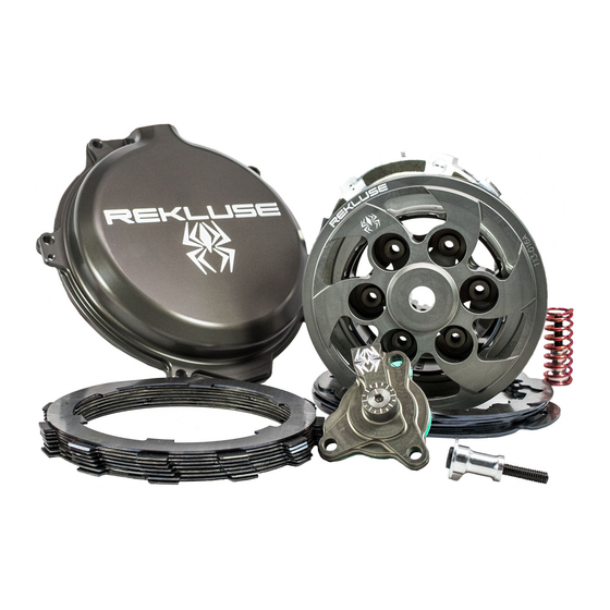
Page 6: Included Parts
INCLUDED PARTS Visit www.rekluse.com/support a full parts fiche illustration and part numbers. Pg. 6 Doc ID: 191-7905A Doc Rev: 081717... -
Page 7: Disassemble The Clutch
DISASSEMBLE THE CLUTCH 1. Turn the fuel petcock to “OFF” if applicable. 2. Lay the bike on its left side. Catch any fuel that might drain in a suitable container. 3. Use an 8 mm socket to remove the clutch cover. If your bike has an oil plug, loosen the plug before removing the cover. - Page 8 Be careful that the drive pins do not fall into the engine while disassembling. 5. Use a hammer and large screwdriver to bend down the tabs of the washer tab, then remove the center clutch nut with an impact wrench or breaker bar, and a 27 mm socket. Pg.
-
Page 9: Inspect The Dampers
6. Remove the tab washer. 7. Remove the center hub assembly from the steel basket while leaving the thrust washer on the main shaft. Check that the thrust washer is still on the main shaft and not stuck to the bottom of the center hub assembly. Missing the thrust washer will cause clutch performance issues. -
Page 10: Install Hubs
2. Rotate the inner hub back and forth inside the outer hub. Rekluse recommends replacing the dampers if you feel any play between the two hubs – KTM part number #78132025100. INSTALL HUBS 1. Remove the 6 rubber dampers from the OE center hub assembly. - Page 11 2. Install the 6 OE rubber dampers and inner hub onto the Rekluse outer hub. 3. Install the new center hub assembly into the motorcycle. 4. Reinstall the OE tab washer and center clutch nut. For 450SX-F/XC-F models, use the supplied lock tab washer in place of OE lock tab washer.
-
Page 12: Clutch Pack Installation
6. Using the channel-lock pliers, bend up both tabs of the tab washer around the nut. 7. Seat the 6 OE drive pins into the Rekluse outer hub. CLUTCH PACK INSTALLATION Each clutch pack comes with a set of steel plates, a set of friction disks, and an EXP disk. - Page 13 1. Soak the friction disks and EXP disk in new oil for at least 5 minutes. Make sure the EXP and friction disks are coated on both sides. Install a steel TEC drive plate by first aligning the drive pin notches in the plate with the drive pins on the hub.
- Page 14 Place the steel plates in the orientation shown with the shark fin notches facing to the right. All drive plates will follow this orientation. Shark fin notches Proper orientation of the drive plates is critical for optimal clutch performance. If you install them backwards, the clutch will still function but will lack proper modulation performance.
- Page 15 *Refer to the Setup Sheet included with the clutch kit for the “Clutch Pack Height” specifications. Pg. 15 Doc ID: 191-7905A Doc Rev: 081717...
- Page 16 6. Install the EXP disk on top of the last steel plate. Make sure that the EXP disk is seated in the same slots as the clutch pack. Some OE basket have “half slots” at the top of the basket tangs. Rekluse products require the entire clutch pack, including the EXP disk, be installed into the MAIN (deeper) basket slots.
-
Page 17: Pressure Plate Installation
PRESSURE PLATE INSTALLATION 1. Add a light film of oil between the lining plate and pressure plate. This will help the plates stick together for ease of installation. 2. Install the supplied lining plate onto the pressure plate by lining up the index tabs into the slots. - Page 18 4. Place the OE slider ring on the pressure plate with the “top” marking facing up. (The top side is rounded and the bottom edge is sharp.) Pg. 18 Doc ID: 191-7905A Doc Rev: 081717...
- Page 19 5. Place the OE Belleville spring onto the slider ring, with the rounded dome side facing up. The outer edge of the Bellville spring will make contact with the slider ring. If it does not, the Bellville spring is upside down. Correct –...
- Page 20 6. Install the OE pressure ring, flat side up. There are 3 possible settings on the OE pressure ring. Please refer to the Setup Sheet for optimized pressure ring setting. For a simple setting, set it to setting II (4-strokes and 2017 + 2- strokes) or X (pre 2017 2-strokes).
- Page 21 9. Remove the OE cover gasket from the OE clutch cover and install it onto the new Rekluse clutch cover. 10. Install the Rekluse clutch cover by lightly tightening the cover bolts in a star pattern. Tighten bolts in small increments before torquing the cover bolts to OE specifications.
-
Page 22: Slave Cylinder Installation
SLAVE CYLINDER INSTALLATION Installing the new Rekluse slave cylinder takes several steps. Please read the entire section before beginning the process to ensure you have the right equipment and clutch fluid needed for the replacement. Rekluse recommends wearing gloves and safety glasses for the install. - Page 23 2. Use your thumbs to compress the piston until it bottoms out, then release it. Pour the recommended clutch fluid into the slave cylinder port. Be sure to use the correct clutch fluid. Check the cap of the clutch master cylinder to determine which clutch fluid to use. Failure to use the correct fluid will result in seal damage and/or failure.
- Page 24 5. Use the wrench to turn the adjuster screw counterclockwise back to the initial position, with the top O-ring visible. Keep the fluid topped off as you go. 6. Use your thumbs to compress the piston again until it bottoms out while looking for air bubbles.
-
Page 25: Step 2: Replace Oe Slave Cylinder
10. Check that the ball bearing is still in place. Stand the Rekluse slave cylinder in an upright position (so the fluid does not spill) until it is needed in the next step. Step 2: Replace OE slave cylinder In this step, the OE slave cylinder is replaced with the Rekluse slave cylinder. - Page 26 3. Remove the clutch fluid line and the 2 OE crush washers from the OE slave cylinder. 2017+ FE450/501: • Remove the OE fluid line fitting. 4. Set the banjo bleeder bolt and the OE crush washer aside. They will not be reused. Fluid line fitting OE slave cylinder...
- Page 27 A quick transfer of the fluid line will result in less bleeding in the following steps. Rekluse banjo bolt Fluid line fitting Rekluse crush washers 2017+ FE KTM 450/500 450/501 FC/FX 450/501 6. Tighten the banjo bolt (or fluid line fitting) with your hand until snug.
- Page 28 8. With the clutch fluid line attached to the Rekluse slave cylinder, remove the OE slave cylinder from the engine. Keep the OE bolts for reuse. 9. Mount the Rekluse slave cylinder to the engine using the OE bolts. Some models have a piston diaphragm seal. DO NOT REUSE them if OE equipped.
- Page 29 The Rekluse slave cylinder comes preassembled in the kit. If the parts become separated, assemble them in the following order: Rekluse slave cylinder, O-ring, then the supplied paper gasket. 10. Torque the banjo bolt to 18 ft-lb (25 N-m) per OE specification. •...
- Page 30 11. Attach the supplied bleed tube to the banjo bolt port and loop it into a suitable catch bottle. 12. Pump the clutch lever 3-5 times then hold it against the bar/grip. 13. Using an 8mm wrench, open the bleed port. Air and fluid should come out of the bleed tube.
- Page 31 14. Slowly release the clutch lever and check the fluid level in the clutch master cylinder. 15. Repeat the previous 3 bleeding steps until air no longer comes out of the bleed port. Then, check that the clutch lever functions properly.
-
Page 32: Set The Installed Gap And Verify By Checking Free Play Gain
SET THE INSTALLED GAP AND VERIFY BY CHECKING FREE PLAY GAIN It is very important that you understand how to set the installed gap in your new clutch, and be able to verify the installed gap by checking Free Play Gain. Setup, break-in, and rechecking the installed gap is CRUCIAL. -
Page 33: Step 1: Find The Starting Point
Setting the installed gap and checking Free Play Gain is a 4-step process. It is important to follow each step to ensure that your new clutch functions as designed. Step 1: Find the starting point a) With the bike standing up, locate the adjuster screw in the center of the adjustable slave cylinder. -
Page 34: Step 2: Learn How To Check Free Play Gain
Use the tick marks on the cylinder and the etch mark on the screw to remember the starting point for adjusting the gap. d) Use a 4 mm Allen wrench to turn the adjuster screw clockwise 1 full turn + 2 tick marks from your starting point. This may NOT be your final setting, but it is a beginning adjustment for finding the correct setting. - Page 35 installed gap. The amount of Free Play Gain you feel in the lever corresponds to the amount the pressure plate has been lifted by the EXP disk expansion. Checking Free Play Gain allows you to externally monitor the installed gap so you can know when to make an adjustment if the installed gap is too large or too small.
-
Page 36: Two Ways To Check For Free Play Gain
Two Ways to Check for Free Play Gain The following steps explain 2 ways to check Free Play Gain. One way uses the rubber band Rekluse includes in the clutch kit, and one uses your hand. You can use either method to check for Free Play Gain. - Page 37 b) Stretch the included rubber band between your thumbs, then place the top end of the rubber band on the outer end of the left handlebar grip. c) While holding the top end of the rubber band against the handlebar, stretch the band downward, then loop it through itself.
- Page 38 d) Pull the band through the loop, then attach it to the outside end of the clutch lever. This will take up the initial free play (slack) and put the lever in a position to detect the Free Play Gain. e) While still in NEUTRAL, quickly rev the engine between 5,000- 7,000 RPM (1/2 to ¾...
-
Page 39: The Hand Method
f) When the bike returns to idle, rest your hand across the clutch lever. Rev the engine again to 5,000-7,000 RPM so you can observe the movement while feeling for Free Play Gain with your hand. The Hand Method Use the hand method to check Free Play Gain before the start of every ride for optimum performance and longevity of your new clutch. - Page 40 b) With the bike at idle, apply enough pressure to the clutch lever to take up the initial free play (slack) in the clutch lever. c) While still in NEUTRAL, continue to apply light pressure and quickly rev the engine between 5,000-7,000 RPM (1/2 to ¾ throttle), then let it return to idle.
-
Page 41: Step 3: Break-In The New Clutch
The lever may move more than 1/8” (3 mm) toward the handle when the engine is revved because there is too much Free Play Gain (movement of the clutch lever). This changes as you adjust the installed gap. Step 3: Break-in the new clutch Once you install your new clutch, it is important to break it in. - Page 42 4. With the bike idling in first gear, slowly apply throttle to begin moving. 5. Without using the clutch lever, accelerate moderately to approximately 10 roll-on starts 5,000 RPM to fully lock up the clutch and come to a complete stop. Repeat 10 times.
-
Page 43: Step 4: Adjust The Installed Gap And Recheck Free Play Gain
7. Place the bike in NEUTRAL and recheck Free Play Gain. 8. Continue to step 4 to adjust the installed gap until the Free Play Gain of the clutch lever is 1/8” (3 mm). Recheck Free Play Gain and adjust the installed gap Your clutch pack will expand with heat, so final adjustment to Free Play Gain should... - Page 44 Tick marks are located on the slave cylinder, and an etch mark is on the screw. If you need to re-position the Allen wrench, you can use these marks for reference. c) Continue to adjust the slave cylinder 1 tick mark at a time until optimal Free Play Gain is achieved.
-
Page 45: Free Play Gain Adjustments
FREE PLAY GAIN ADJUSTMENTS Make each adjustment in small increments - one tick mark at a time. After each adjustment, recheck Free Play Gain until you achieve the optimal 1/8” (3 mm) of clutch lever movement. Symptom Reason Solution • Clutch lever moves in too far (too much Free Turn the adjuster screw Play Gain) -
Page 46: Maintenance
MAINTENANCE To keep your clutch performing at its best, perform regular maintenance on your bike and clutch. • Keep up with regular oil changes as per the bike manufacturer’s recommendations. Clutch performance and longevity depend on oil quality. Oil recommendations can also be viewed under Tech Tips on our website at www.rekluse.com/support/videos/atv-mc-support- videos. - Page 47 • Inspect the dampers, and replace them if you feel any movement between the two hubs. Refer to the section on inspecting the dampers for more information. • Maintain adequate Free Play Gain. Check before every ride and adjust if necessary. •...
-
Page 48: Disk Inspection Examples
Disk inspection examples When inspecting the clutch pack, the following pictures can be used as a reference. These are best viewed in color by viewing this install document from www.rekluse.com/support. Drive Plates – If the clutch pack is getting high amounts of heat, purple, blue, or black color can be seen on the drive plate teeth. -
Page 49: Troubleshooting
TROUBLESHOOTING Performance issues If you find yourself adjusting the slave cylinder to fix Free Play Gain or drag, the clutch disks might be worn. Excessive heat or clutch slip can cause premature clutch failure as well. Once extreme temperatures are reached, irreversible damage will occur. •... -
Page 50: Changing The Springs
idling in gear and warmed up. The idle should not be so high as to move the bike forward in gear with the throttle closed. However, with a small opening of the throttle the bike should move forward. You can tune the engagement RPM of the EXP disk by changing the spring configuration. - Page 51 To maintain even pressure, when using two different color spring sets, install one set of 3 on one side of the EXP and the remaining set of 3 on the other side. If you disassemble the EXP, the Teflon pads may fall out or be stuck to the ramp surfaces of the EXP bases.
-
Page 52: Configuration Chart
Configuration chart ENGAGEMENT SPRING CONFIGURATION SETTING 450/500/501 250/300 250/300 250/350 4-stroke 2-stroke 2-stroke EXC-F/ (Pre 2017) (2017+) XCF-W 6 Steel 6 Silver 6 Blue 6 Silver 3 Silver & 3 3 Silver & 3 Blue & 3 3 Silver & Medium Steel 3 Red... -
Page 53: Doc Rev:
NEED ADDITIONAL HELP? Website www.rekluse.com/support Frequently asked questions www.rekluse.com/faq Support Videos www.rekluse.com/support/videos Phone (208) 426-0659 Technical Support Contact Technical Support for questions related to product installation, tuning, and performance. Technical Support hours: Monday thru Friday: 8:00 a.m. - 5:00 p.m. Mountain Time zone Email: tech@rekluse.com Customer Service...
Need help?
Do you have a question about the Radius CX Clutch and is the answer not in the manual?
Questions and answers