Table of Contents
Advertisement
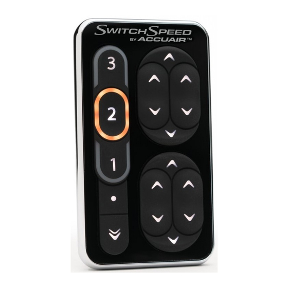
Thank you for purchasing the revolutionary SwitchSpeed™ Controller by
AccuAir.
This air suspension controller manages up to 4 Air Springs as an intelligent
switchbox with user-adjustable control of valve speed. The AccuAir
SwitchSpeed™ also manages your Air Compressor(s) to keep onboard air
at an ideal pressure for your application (If Optional Electronic Tank Pressure
Sensor is connected).
To maximize functionality, the AccuAir SwitchSpeed™ allows you to select
from three distinct valve speeds:
1.) Full Speed.
2.) Medium Speed (Adjustable).
3.) Precision Speed (Adjustable).
The exact settings for each of these speeds is User Adjustable
(see page 10 in your Operation Manual).
!
WARNING: Extended valve pulsing MAY reduce the life of your
At AccuAir, we pride ourselves on thorough customer service, quality
products, and a better driving experience through technologically
superior design.
Operation Manual
SwitchSpeed™ Controller:
Congratulations!
valves.
Advertisement
Table of Contents

Related Manuals for AccuAir SwitchSpeed

Summary of Contents for AccuAir SwitchSpeed
- Page 1 This air suspension controller manages up to 4 Air Springs as an intelligent switchbox with user-adjustable control of valve speed. The AccuAir SwitchSpeed™ also manages your Air Compressor(s) to keep onboard air at an ideal pressure for your application (If Optional Electronic Tank Pressure Sensor is connected).
-
Page 2: Table Of Contents
Table Of Contents Description Page Number Terms & Conditions Service Disable & General Understanding General Operation Setup Programming 9-13 Operation Trouble Indication & Diagnosis 14-15 System Diagram 16-17... -
Page 3: Terms & Conditions
CUSTOMER. Warranty ACCUAIR will repair or replace any failed components for the life of the vehicle given that the components were installed and operated as intended by ACCUAIR. Upon the return of a failed component(s), ACCUAIR will determine the cause of failure. -
Page 4: Service Disable & General Understanding
For simplicity of use and understanding we refer to the four wheels of a vehicle by number. Instead of using “Left Front”, or “Right Front” etc. Refer to the following diagram for labeling: - Page 4 - SwitchSpeed™ Controller Manual V1.3 © 2009 AccuAir Control Systems, L.L.C. -
Page 5: General Operation
” Button momentarily. The Speed #1 “ ” Indicator will be lit solid. Now use the Manual Adjustment Buttons to move the vehicle at this selected speed. - Page 5 - SwitchSpeed™ Controller Manual V1.3 © 2009 AccuAir Control Systems, L.L.C. - Page 6 Arrow Buttons on the right side of the controller. MOMENTARY: Press the All-Down “ ” Button until the vehicle is as low as you desire. - Page 6 - SwitchSpeed™ Controller Manual V1.3 © 2009 AccuAir Control Systems, L.L.C.
- Page 7 Button to FILL both Air Springs #3 & #4 together. Press the Combination #3 & #4 DOWN “ ” Button to EMPTY both Air Springs #3 & #4 together. - Page 7 - SwitchSpeed™ Controller Manual V1.3 © 2009 AccuAir Control Systems, L.L.C.
- Page 8 Press the #3 DOWN “ ” Press the #4 DOWN “ ” Button to EMPTY the Button to EMPTY the #3 Air Spring. #4 Air Spring. - Page 8 - SwitchSpeed™ Controller Manual V1.3 © 2009 AccuAir Control Systems, L.L.C.
-
Page 9: Setup Programming
(Description on Pg. 11) Tank Pressure Mode: (Optional) 150 psi = White only 175 psi = White & Red alternating 200 psi = Red only (Description on Pg. 12) - Page 9 - SwitchSpeed™ Controller Manual V1.3 © 2009 AccuAir Control Systems, L.L.C. - Page 10 NOTE: Use the Paired UP “ ” & Paired DOWN “ ” Buttons to test the current Speed Selection while setting the Valve ON / OFF Time. - Page 10 - SwitchSpeed™ Controller Manual V1.3 © 2009 AccuAir Control Systems, L.L.C.
- Page 11 ALL-DOWN Mode is MOMENTARY. NOTE: Program Mode will exit after 5 seconds or can be exited by pressing the Program Button again and your changes will be saved. - Page 11 - SwitchSpeed™ Controller Manual V1.3 © 2009 AccuAir Control Systems, L.L.C.
- Page 12 Arrows are OFF. NOTE: Program Mode will exit after 5 seconds or can be exited by pressing the Program Button again and your changes will be saved. - Page 12 - SwitchSpeed™ Controller Manual V1.3 © 2009 AccuAir Control Systems, L.L.C.
- Page 13 ” Button to make the Backlighting DARKER. NOTE: Program Mode will exit after 5 seconds or can be exited by pressing the Program Button again and your changes will be saved. - Page 13 - SwitchSpeed™ Controller Manual V1.3 © 2009 AccuAir Control Systems, L.L.C.
-
Page 14: Operation Trouble Indication & Diagnosis
• Check for Compressor failure. • Check for Pressure Sensor failure. Pressure Sensor is not reading. • Verify wiring to Pressure Sensor. • Check Pressure Sensor for failure. - Page 14 - SwitchSpeed™ Controller Manual V1.3 © 2009 AccuAir Control Systems, L.L.C. - Page 15 If the vehicle system voltage drops below 10.5 volts during operation, the SwitchSpeed™ will automatically turn the compressor(s) OFF and show the trouble indication below. The SwitchSpeed™ will go back to normal operation once the vehicle system voltage reaches 12.5 volts or the ignition is cycled.
- Page 16 - Page 23 - - Page 17 - - Page 3 - - Page 5 - - Page 5 - SwitchSpeed™ Controller Manual V1.3 © 2009 AccuAir Control Systems, L.L.C. SwitchSpeed™ Controller Manual V1.3 © 2009 AccuAir Control Systems, L.L.C.
- Page 17 This air suspension controller manages up to 4 Air Springs as an intelligent switchbox with user-adjustable control of valve speed. The AccuAir SwitchSpeed™ also manages your Air Compressor(s) to keep onboard air at an ideal pressure for your application (If Optional Electronic Tank Pressure Sensor is connected).
- Page 18 CUSTOMER. Warranty ACCUAIR will repair or replace any failed components for the life of the vehicle given that the components were installed and operated as intended by ACCUAIR. Upon the return of a failed component(s), ACCUAIR will determine the cause of failure.
- Page 19 SwitchSpeed™ Controller (Main) 70Amp Fuse 12 V Batt (F1) 10 Amp ECU Fuse BATT_12V Compressor(s) (F2) 3 Amp Relay Compressor Relay Fuse When using other MFG’s COMP_1 valves: P_SENS Compressor 1 Compressor 2 (Optional) V_GND 1.) Up 4 White/Black 2.) Up 3 White/Orange 3.) Up 2...
- Page 20 Installation Overview: After your Air Springs and Suspension Components have been installed, you can begin installing the AccuAir components in the following order: Install VU4 (Valve Unit) Install ECU (Electronic Control Unit) Install SwitchSpeed™ Controller Install Tank Pressure Sensor (Optional)
- Page 21 VU4 (Valve Unit) Mounting: Valve Mounting Considerations • These valves are 100% weather-proof and can be mounted under vehicle. • You will need to mount the ECU near the valves, so make sure that there is enough space for both items. Step-by-Step 1.) Find a flat location to mount the VU4.
- Page 22 ECU Mounting: ECU Mounting Considerations • The ECU is 100% weather-proof and can be mounted under vehicle next to the valves. • The ECU can be mounted upright or on its back as seen below. (If back mounted, back tabs must be removed) •...
- Page 23 Example 1: Pressure Sensor Mounting. (In the top of the tank) Air Tank WARNING: Optional compressor control require use of an AccuAir Pressure Sensor. System cannot be connected to any other brand of Pressure Sensor or Pressure Switch. Step-By-Step 1.) Coat the threads of the Sensor and any threaded fitting or adapter used in the air supply system with a thread sealer to help prevent air leaks.
- Page 24 Installing & Wiring Air Compressor(s): Air Compressor(s) Mounting Considerations • There should be a fuse in between the Compressor(s) and the battery. • The Compressor(s) get very HOT during operation. Make sure to leave space between items that are susceptible to heat. (Wires, Nylon-Air Line, etc.) Step-By-Step 1.) Find a location for the Compressor(s) to be mounted with good air circulation.
-
Page 25: System Diagram
1.) First connect the Main Harness at the ECU then route each section to each component on the vehicle. 2.) Route the SwitchSpeed™ harness (Mini USB Cable) to the inside of the vehicle and leave until later in installation. Route the single purple wire labeled “HEADLIGHTS”... - Page 26 SwitchSpeed™ Controller Mounting: SwitchSpeed™ Controller Mounting • Choose a mounting location that will allow the driver to operate and view the SwitchSpeed™ Controller from the driver’s seat. Once your target mounting position has been found, use the template to drill mounting holes.
- Page 27 Now your system components are installed, plumbed, and wired (Mechanical Air Suspension Components, Compressor(s), Tank(s), Tank Pressure Sensor, Valves, Air Line, ECU, and SwitchSpeed™ Controller), it is time to test the system. To Begin Testing The System: Turn the vehicle Ignition ON, or start the vehicle.
- Page 28 Mounting Templates: 2.45 Drill Size: 13/64” #6,#7,#8 VU4 (Valve Unit) Mounting Template.
- Page 29 Drill Size: 13/64” #6,#7,#8 1.50 Bottom ECU Mounting Template. (Standard) Minimum leave clear space for connectors...
- Page 30 2.02 1.01 Drill Size: 13/64” #6,#7,#8 Rear ECU Mounting Template. (Optional)
- Page 31 TOP VIEW Drill Size: 5/32” SwitchSpeed™ Mounting Template. Bottom Side with USB Connector Accept no compromises, choose only quality performance suspension parts.
Need help?
Do you have a question about the SwitchSpeed and is the answer not in the manual?
Questions and answers