Advertisement
Quick Links
APPLICATION REQUIREMENTS:
Available to all limited duty commercial door operators using the Logic control board. Example model identifier: MT-5011-U.
NOTE: For B2 wiring mode, these boards require a monitored safety device installed.
1. Disconnect power to operator.
2. Remove all wires from the existing logic board:
• Unplug Factory Wiring Connector (P1).
• Field control wiring from terminal strip.
NOTE: Remember location of all wiring connections for
reinstallation.
3. Remove the logic board from the mounting posts (5).
4. Install the new logic board into the operator, making sure that
the logic board is correctly oriented. Press firmly until all of
the mounting posts are completely through the mounting
holes and secure the board with the plastic nuts (2).
5. Plug factory wiring connector into P1 connector on logic
board.
6. Reconnect all field wiring to the field wiring terminal strip.
7. Make sure the electrical box is clear of all debris and tools.
8. Reconnect power to the operator and verify operation. Refer to
page 2 to reprogram remote controls and settings as
necessary.
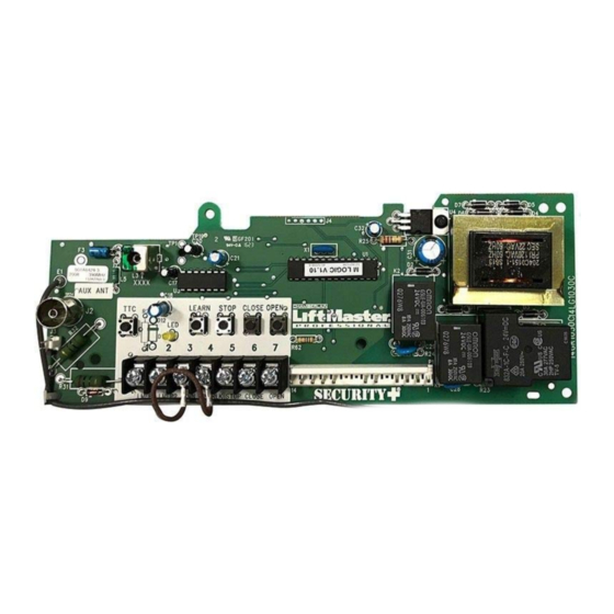
LOGIC CONTROL BOARD
Purple Wire Antenna
AUX ANT
AUX ANT
Auxiliary
J2
Antenna
Connection
D9
I N S T A L L A T I O N
Learn
Stop
Timer to Close
Button
Button
Button
C20
2
TP1
C9
L5
^^
^^^^
C18
R27
D14
TTC
LEARN
DIAGNOSTIC
LMEP1 LMEP2
COM
INTRLK
1
2
3
4
Diagnostic LED
Field Wiring Terminal
To avoid SERIOUS personal INJURY or DEATH from
electrocution, DISCONNECT electrical power to operator
BEFORE proceeding.
www.devancocanada.com
or call toll free at 855-931-3334
Close
Open
Button
Button
J4
014A1030
3
C21
STOP CLOSE OPEN
STOP CLOSE OPEN
5
6
7
Factory Wiring Connector (P1)
1
LOGIC BOARD
REPLACEMENT KIT
K1A6424 (315MHZ)
K1A6424-1 (390MHZ)
For more information:
D7
U4
D6
C32
R25
U1
K2
LT
C29
R24
P1
D5
D4
Advertisement

Related Manuals for Chamberlain K1A6424


Summary of Contents for Chamberlain K1A6424
-
Page 1: Logic Board
LOGIC BOARD REPLACEMENT KIT K1A6424 (315MHZ) K1A6424-1 (390MHZ) APPLICATION REQUIREMENTS: Available to all limited duty commercial door operators using the Logic control board. Example model identifier: MT-5011-U. NOTE: For B2 wiring mode, these boards require a monitored safety device installed. - Page 2 Tested to Comply with FCC Standards FOR HOME OR OFFICE USE. Operation is subject to the following two conditions: (1) this device may not cause harmful interference, and (2) this device must accept any interference received, including interference that may cause undesired operation. © 2008, The Chamberlain Group, Inc. 01-34371 All Rights Reserved...
-
Page 3: Repair Parts
HOW TO ORDER REPAIR PARTS DEVANCO CANADA 19192 HAY ROAD, UNIT Q SUMMERSTOWN, ON K0C 2E0 TOLL FREE: 855-931-3334 www.devancocanada.com WHEN ORDERING REPAIR PARTS PLEASE SUPPLY THE FOLLOWING INFORMATION: 3 PART NUMBER 3 DESCRIPTION 3 MODEL NUMBER...