Table of Contents
Advertisement
Advertisement
Table of Contents

Related Manuals for Permobil ICS

Summary of Contents for Permobil ICS
- Page 1 TECHNICAL MANUAL ICS Onboard Configuration...
- Page 3 Head Office of the Permobil group Permobil AB Box 120 861 23 Timrå Sverige Tlf. +46 60 59 59 00 Fax +46 60 57 52 50 E-mail: info@permobil.se Produced and published by Permobil AB, Sweden Edition: 8, 2015-09 Order no. 205247-US-0...
-
Page 4: Table Of Contents
General ............................21 ICS Switchbox programming ..................... 21 R-net control panel programming ..................... 21 PC programming ........................21 Configuring using the ICS Switchbox ....................22 Global settings .......................... 22 Selecting a user weight range ....................22 Selecting the LED indication level ..................... 24 Switchbox label sheet ....................... - Page 5 Performing automatic actuator calibration ................. 57 Performing manual actuator calibration ..................59 Transportation (WC19) mode hook position ................60 Configuring ICS through R-net control panel ................. 61 Enabling the ICS menu in OBP ....................61 Changing the seat function order in Seating Mode ..............62 Limiting the seat’s permitted movements .................
-
Page 6: Chapter 1 - Operation
Chapter 1 - Operation Introduction General The Intelligent Control System (ICS) controls the Powered Seat Functions and provides Drive Inhibit information to the Driving System. System Hardware The Intelligent Control System consists of the following components. Please note, not all components are used in all configurations. -
Page 7: Controls And Feedback
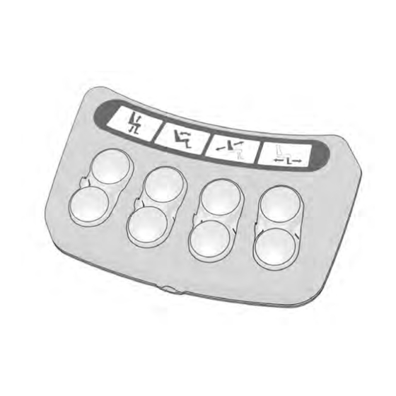
Operation Controls and Feedback Controls and Feedback Controls and Feedback There are two styles of ICS Switchbox, Pushbutton or Toggle, each offers the same functionality Toggle Switchbox Pushbutton Switchbox Switchbox Layout The functionality of the buttons in the switchbox is programmable. Different switchbox layouts are available for each seating system. -
Page 8: Icons
Operation Controls and Feedback Icons The ICS uses Icons to represent Seat Functions and System Features. Each Icon used in the ICS is explained below. Please note that not all icons are used in every seat configuration. Seat Elevator Power Recline... -
Page 9: Switchbox Leds
Operation Controls and Feedback Switchbox LEDs In addition to the button symbols, the switchbox provides feedback through its built-in LEDs. Each button and function has its own LED. The information presented by the LEDs is related to available seat function, active seat function inhibit, active drive speed limit, active drive inhibit and system errors. There are three light states that the LED above the switch can have, Off, Solid or Flashing. -
Page 10: Switchbox Led Colors And Their Meanings
Switchbox is currently in, the functionality of each switch can be different. When using the ICS Switchbox, it is important to note the Position, Color and “Light Type” (Solid/ Flashing) of the LEDs that illuminate the Icons on the Switchbox. - Page 11 Operation Basic Seat Operation through Switchbox Switchbox Examples Solid Solid Solid Yellow Green Green The indications on the switchbox above communi- cate: • Switches 2 & 6 will operate the Seat Elevator • Switches 1 & 5 will not operate a Seat Function •...
-
Page 12: Advanced Seat Operation Through Switchbox
Depending on the Switchbox Layout that has been selected and the mode that the Switchbox is currently in, the functionality of each switch can be different. When using the ICS Switchbox, it is important to note the Position, Color and “Light Type” (Solid/ Flashing) of the LEDs that illuminate the Icons on the Switchbox. -
Page 13: Seat Function Memory Step-By-Step
Operation Advanced Seat Operation through Switchbox Seat Function Memory Step-by-Step Storing a Seating Position into Memory Button 4 “Enable Store” Button 5-7 “STORE” Button 8 “Enter/Exit Memory mode” Before beginning: Position the seating system in the desired position using the techniques described in the Controlling Seat Functions section. - Page 14 Operation Advanced Seat Operation through Switchbox Seat Function Memory Step-by-Step Recalling a Seating Position from Memory Button 1-3 “RECALL” Button 8 “Enter/Exit Memory mode” 1. Enter the memory mode by pressing and holding Button #8 for two seconds. the floppy symbol flashes green (this signifies that you are in the memory mode) 2.
-
Page 15: Basic Seat Operation Through R-Net Control Panel
Operation Basic Seat Operation through R-net Control Panel Basic Seat Operation through R-net Control Panel Seating System movement can be performed using the Joystick in the Control Panel that operates the wheelchair drive motors. Seating Control is accessed via the MODE button on the Control Panel. -
Page 16: Advanced Seat Operation Through R-Net Control Panel
Operation Advanced Seat Operation through R-net Control Panel Advanced Seat Operation through R-net Control Panel Recalling a Seat Position from Memory Seat Position Memories can be recalled using the Joystick in the Control Panel that operates the wheelchair drive motors. The Seat Position Memories are part of the Seating Control Mode. -
Page 17: Storing A Seat Position In Memory
NOTE! Before storing a seating position, it is important that the seat is in the position you wish Normal to be memorized. Position the seat (via the ICS Switchbox or R-net Joystick) before continuing below. Once in the Seating Mode, push the joystick left... -
Page 18: Standing Function (Only Applies To Vs Seat)
The VS Seating System is capable of transitioning Solid from a seated or partially reclined position to a fully Green standing position via the use of an ICS Switchbox button or through the Control Panel. Standing Operation through Switchbox Using the ICS Switchbox to operate the Standing Sequence with Layout 2: •... - Page 19 Operation Standing Function (Only applies to VS Seat) Solid Using the ICS Switchbox to operate the Standing Green Sequence with Layout 4: • Switch 1 will stand the chair according to Standing Sequence ‘A’ • Switch 5 will unstand the chair according to Standing Sequence ‘A’...
-
Page 20: Standing Operation Through Pilot+ Joystick
Operation Standing Function (Only applies to VS Seat) Standing Operation through Pilot+ Joystick (VS seat only) Seat Movement of the VS Seating System can be performed through the Joystick in the Control Panel used to operate the wheelchair’s drive motors. Seating Control is accessed via the MODE button on the Control Panel. -
Page 21: Chapter 2 - Programming
PC Programming It is also possible to configure the ICS system using a PC based software application created by Permobil. To use a PC to configure the ICS system in a wheelchair, you must have the necessary software and cabling. -
Page 22: Configuring Using The Ics Switchbox
These Settings are available on every wheelchair equipped with ICS. Selecting a User Weight Range The ICS System must be programmed with the user’s weight in order to provide the safest and most reliable configuration possible. The user weight information is used to limit the maximum position of some actuators, resulting in a more reliable seating system and a safer overall product configuration. - Page 23 To enter the User Weight Entry mode, the system needs to be started up with a combination of pressed buttons: Press and hold Button 2 and Button 4 on the ICS Switchbox, while holding these buttons, turn on the wheelchair with the Power Button on the Joystick (or Input Device).
-
Page 24: Selecting The Led Indication Level
The type of indication that is given by the LEDs inside the ICS Switchbox can be adjusted. If perhaps, a user is easily distracted by the flashing indications, these can be hidden by selecting Indication Level 2. -
Page 25: Switchbox Label Sheet
Programming Configuring using the ICS Switchbox Switchbox Label Sheet For ease of programming, the Layout Numbers for each Label included in Part Number 1822329 are shown. Corpus II & Corpus 3G – Layout 1 Corpus APE & Corpus VS – Layout 1 RS –... -
Page 26: Choosing A Switchbox Layout
1. Enter the Switchbox Layout Selection mode: a) With the wheelchair off, press and hold Button 1 and Button 3 on the ICS Switchbox. b) While holding these buttons, turn on the wheelchair with the Joystick (or Input Device) Power Button. - Page 27 Programming Configuring using the ICS Switchbox Number of lit LEDs Solid Green Solid Red Solid Yellow Layout 1 Layout 7 Layout 13 Layout 2 Layout 8 Layout 14 Layout 3 Layout 9 Layout 15 Layout 4 Layout 10 Layout 16...
-
Page 28: Other General Settings
Press and hold buttons 2, 7 and 8 on the ICS Switchbox while powering up the wheelchair by pressing the start key on the control panel. The ICS Switchbox buttons can be released once all its LEDs light up green. You can now access page 1 of the Set-up settings. - Page 29 When LED 3 lights up red, the elevator will move up when the front button is activated. (standard). Inverting the tilt direction through the switchbox To adjust whether the direction of the tilt will be inverted when operated with the ICS switchbox, press button 6.
- Page 30 Programming Configuring using the ICS Switchbox Inverting Recline direction through the switchbox To adjust whether the direction of the recline will be inverted when operated with the ICS switchbox, press button 3. • When LED 5 lights up green, the recline will move forward when the rear button is activated.
-
Page 31: Corpus Ii Specific Attributes
Selection mode, the system needs to be started up with a combination of pressed buttons: Press and Solid Green hold Button 1, 2 and 7 on the ICS Switchbox, while 6° holding these buttons, turn on the wheelchair with the Power Button on the Joystick (or Input Device). -
Page 32: 45° Tilt Calibration C400/C500 Corpus
2. The system needs to be started up with a combination of pressed buttons: Press and hold Button 5, 6 and 3 on the ICS Switchbox, while holding these buttons, turn on the wheelchair with the Power Button on the Control Panel (or Input Device). -
Page 33: Corpus 3G - Specific Attributes
Programming Corpus 3G/HD/APE/VS - Specific Attributes Corpus 3G/HD/APE/VS - Specific Attributes IRM - Independent Repositioning Mode The IRM-function has been designed to make it possible for the user to regain the best seated position with the whole back leaning against the backrest. The function consists of two parts. First a movement (A) which makes the user lean back and slide towards the back rest. - Page 34 With the power turned off, press button 2, 7 and 8 on the ICS control panel. • Turn the power on by pressing the start button on the wheelchair’s control panel. ICS-control panel buttons can be released when all the LEDs are lit green. •...
- Page 35 With the power turned off, press button 5 and 7 on the ICS control panel. • Turn the power on by pressing the start button on the wheelchair’s control panel. ICS-control panel buttons can be released when all the LEDs are lit green.
- Page 36 Programming Corpus 3G/HD/APE/VS - Specific Attributes The user’s handling of the IRM Method A) Via ICS control panel with ”memory mode”: • HolPress and hold button 8 to enter the memory mode. LED 8 is blinking green. • Press and hold button 3 to move the seat to it’s rear position.
-
Page 37: Setting Of Corpus 3G Seat Depth
1. To enter the Seat Depth Selection mode: a) With the wheelchair off, press and hold Buttons 3, 4 & 6 on the ICS Switchbox b) While holding these buttons, turn on the wheelchair c) When all LEDs on the ICS Switchbox turn green, release the buttons. -
Page 38: Corpus 3G On M300/M400 Och C350
Programming Corpus 3G/HD/APE/VS - Specific Attributes Corpus 3G on M300/M400 and C350 Corpus HD on M300/M400 Adjusting Legrest Angle for Full-Speed Driving When the Corpus 3G Seating System is mounted to a Power Base that has front casters, it is possible for the footplates to interfere with the swiveling of those casters. - Page 39 1. Enter Legrest Angle Offset Adjustment mode: +12° a) With the wheelchair off, press and hold offset Buttons 1, 2 & 7 on the ICS Switchbox. +9° b) While holding these buttons, turn on the wheelchair with the Joystick (or Input offset Device).
-
Page 40: Corpus Vs/Corpus Ape - Specific Attributes
While holding these buttons turn on the wheelchair with the Power Button on the control panel (or Input Device). d) Once all LEDs on the ICS Switchbox turn green, release Buttons 5 and 7. LED #8 will be blinking RED/GREEN. - Page 41 Button 3 and 7: for adjustment of legrest angle • Button 8: Save Indications on the ICS Switchbox (CPx = CheckPoint x) • Led 1 - solid green: CP1 can be saved. CP1 is the highest position where the seat is still horizontal during the raising part.
- Page 42 Button 3 and 7: for adjustment of legrest angle • Button 8: Save Indications on ICS Switchbox (CPx = CheckPoint x) • Led 1 – solid yellow: CP1 can be saved. CP1 is the highest position where the seat is still horizontal during the raising part.
- Page 43 Programming Corpus VS/APE- Specific Attributes 4. Adjustment of Legrest extension in standing position (Only Corpus VS and Power transfer option on Corpus APE) This sequence is entered by pressing Button 3 in Standing Sequence Setting mode (Led 3 = solid green). Note: If the button is pressed for more than 15s and the seat angle is not negative (angled forwards), the legrest extension will be reset to the default extension in standing position.
- Page 44 Programming Corpus VS/APE- Specific Attributes 5. Ground Clearance and Ground Touch adjustments: Both these sequences are entered by pressing Button 4 in Standing Sequence Setting mode (Led 4 = solid green, Led 8 = flashing yellow) The Ground Clearance setting together with the Ground Touch are used by the system to maintain footplate ground clearance during standing.
-
Page 45: Vs Specific Attributes
To change to Stand NO drive the system needs to be started up with a combination of pressed Buttons Press and hold Button 1, 2 and 7 on the ICS Switchbox, while holding these buttons, turn on the wheelchair with the Power Button on the Joystick (or other Input Device). - Page 46 Programming VS - Specific Attributes 3. Begin programming the desired sequence: When using Switchbox Layout 1 (sticker D), Layout 2 (sticker E) or Layout 3 (sticker F): a) Press and hold Button #1, #2 or #3 to select the desired pre-defined sequence. b) The left part of the symbol above the button will glow green.
- Page 47 Programming VS - Specific Attributes 4. Operate the standing sequence and adjust the footplate clearance: a) Press Button #1 to begin standing the seat. b) Watch the footplate wheels as the seat is stood, raise the Seat Elevator using Button #2 to prevent the footplate wheels from colliding with the ground. c) Continue to use Button #1 to stand the seat until the Stand Angle is at the desired position.
- Page 48 Programming VS - Specific Attributes 6. Test the settings for proper operation: a) After the standing information has been stored, turn the chair off and back on again. b) Test the Standing Sequence using the appropriate switches or the joystick) c) Confirm that everything works as expected.
- Page 49 Programming VS - Specific Attributes Pre-Defined Standing Sequences Pre-Defined 2: Tight “Sit to Stand” This sequence is similar to the Default 1, except the backrest and legrest angles are more “contracted”. This results in a faster transition to standing, where the backrest angle opens less while the seat pan angle increases.
- Page 50 Programming VS - Specific Attributes Pre-Defined Standing Sequences Pre-Defined 3: “Lay to Stand” This sequence is similar to a “Tilt Table” Stander. First, the backrest and legrest are moved to 180°. Then the seat pan angle is transitioned to the vertical position, much like a tilt board.
-
Page 51: Setting Legrest Type
To enter the Legrest Selection mode, the system needs to be started up with a combination of pressed buttons: Press and hold Button 1, 2 and 7 on the ICS Switchbox, while holding these buttons, turn on the wheelchair with the Power Button on the Joystick (or Input Device). -
Page 52: Setting Optional Tilt
To enter the Tilt Selection mode, the system needs to be started up with a combination of pressed buttons: Press and hold Button 1, 2 and 7 on the ICS Switchbox, while holding these buttons, turn on the wheelchair with the Power Button on the Joystick (or Input Device). -
Page 53: K450 Specific Attributes
K450 - Specific Attributes Enabling Transport Position (WC19) Mode The K450 can be equipped with an optional transportation kit. When the transportation kit is fitted, the ICS must be programmed accordingly in order for the wheelchair to operate correctly. If the Transport Position Mode is turned off, the user will not be able to place the K450 in the transportation position before entering a vehicle. -
Page 54: Setting Optional Tilt
To enter the Tilt Selection mode, the system needs to be started up with a combination of pressed buttons: Press and hold Button 1, 2 and 7 on the ICS Switchbox, while holding these buttons, turn on the wheelchair with the Power Button on the Joystick (or Input Device). -
Page 55: Setting Seat Width And Armrest Type
Yellow Green Use the ICS Switchbox to adjust the setting of how low to the ground the seat can move: No Restriction, Seat Pan as low as 3.5”. Use for all Green combinations in table above. Solid Green Some Restriction, Seat Pan no lower than 10”... - Page 56 Changing the Seat Width Setting on K450: 1. Enter the Seat Width Selection mode: a) With the wheelchair off, press and hold Buttons 3, 4 & 6 on the ICS Switchbox. b) While holding these buttons, turn on the wheelchair with the Joystick (or Input Device).
-
Page 57: Performing Automatic Actuator Calibration
Since the ICS controller does not normally allow each actuator to make a “hard stop” at each physical end stop, it is necessary to enter a special mode that will allow this movement. - Page 58 The Automatic Calibration sequence performs several checks to confirm that each of the five calibration steps have been successful. If the ICS detects that a step was not completed successfully, it will give notification of this failure by sounding the R-net joystick’s horn continuously. Note how many LEDs are illuminated on the switchbox and the position of the seating system before turning off the chair to silence the notification (and exit the calibration mode.) Try automatic calibration a second time, if the failure...
-
Page 59: Performing Manual Actuator Calibration
2. Press and hold buttons 6 and 8 on the ICS Switchbox while turning on the wheelchair. 3. Once all the LEDs on the ICS Switchbox show in a green toggling pattern, release the buttons. 4. Press button 6 to move the elevator fully down. Don’t release the button until the actuator makes a “hard stop”... -
Page 60: Transportation (Wc19) Mode Hook Position
Adjusting Hook Position on K450: 1. Enter the Transportation Hook Adjustment mode: a) With wheelchair off, press and hold Buttons 6 & 8 on the ICS Switchbox. b) While holding these buttons, turn on the wheelchair with the Joystick (or Input Device). -
Page 61: Configuring Ics Through R-Net Control Panel
Configuring ICS through R-net control panel Configuring ICS through R-net control panel Additional ICS configuration is possible using R-net’s OBP function. To enable OBP, a programming key (R-net dongle) must be connected to the R-net system. NB! OBP cannot be used with the R-net LED Joystick Module. -
Page 62: Changing The Seat Function Order In Seating Mode
Programming Configuring ICS through R-net control panel Changing the seat function order in Seating Mode It is possible to specify the order in which the icons for the various seat functions appear on the LCD display when scrolling using the joystick in Seating Mode. -
Page 63: Limiting The Seat's Permitted Movements
Programming Configuring ICS through R-net control panel Limiting the seat’s permitted movements As standard the seat’s maximum movements are based on the actuator’s stroke length and the stability of the chair at different configurations, as well as the user’s weight. If you still need to limit the seat’s maximum movements, this can be done... -
Page 64: Adding Or Removing Seat Functions
ICS system in order to ensure full operation. By making corrections in the Avail. Functions menu and specifying the type of seat function installed, the system is usually able to function without any additional re-programming. -
Page 65: Configuring Functions For Alternative Switchbox
Programming Configuring ICS through R-net control panel Configuring functions for Alternative Switchbox It is possible to connect up to 8 buttons to the Alternative Switchbox for control of the chair’s seat functions. This works in parallel with control of the seat functions through normal switchboxes and via the joystick in Seating Mode. -
Page 66: Configuring Ics Through R-Net Pc Programmer
Configuring ICS through R-net control panel Configuring ICS through R-net PC programmer It is possible to achieve the same ICS settings with the R-net PC programmer (Dealer) as with R-net OBP. See the section entitled “Configuring ICS through R-net control panel”. -
Page 67: Chapter 3 - Diagnostics & Troubleshooting
Chapter 3 – Diagnostics & Troubleshooting Diagnostic LED Indications In addition to the LED indications the ICS Switchbox provides the user, there are several “diagnostic level” LED indications that are useful to a technician when troubleshooting the seating functions on a wheelchair with ICS. -
Page 68: Seat Elevator Softpot Error Mode
The Seat Elevator fitted on the VS seating system is equipped with a Soft Pot positioning sensor. This Soft Pot sensor enables the ICS system to determine the exact height of the seat elevator. The height information is used to properly position the seat elevator during a standing sequence and enables storing and recalling of seat position memories. -
Page 69: Chapter 4 - Servicing
Control System must connect to the ICS Bus in order to function. To connect an ICS component to the system, an “open” ICS Port is required. ICS Ports can be found either in the ICS Master Module or in an ICS Connector Block. -
Page 70: Ape-Actuator Recalibration Mode
When the Linak actuator has moved to mechanical end position it is calibrated and triggers a restart request. After restart the seat functions is working normally again. During recalibration mode LED #1 on the ICS switchbox is flashing red/yellow and the buttons have the following functions... -
Page 71: Switchbox Replacement
Programming Replacement of Switchbox, Actuator, General Module Switchbox Replacement Consult Seating System Service Manual. Actuator Replacement Consult Seating System Service Manual. General Module Replacement Consult Seating System Service Manual. -
Page 72: Smart Actuator Calibration
2. The system needs to be restarted by pressing and holding a combination of buttons: Press and hold buttons 5, 6 and 3 on the ICS Switchbox. While doing this, switch the wheelchair on using the power button on the joystick (or input device). - Page 73 Automatic calibration cannot be performed on chairs with “old ICS programs” < v.30 (december 2010) or for functions where the actuator is equipped with SoftPot.
- Page 74 After completing a successful calibration, the system will issue a ”calibration complete-beep” (beep- beep-beep-beep-beeeeeep) to confirm that the calibration is completed. All the LEDs on the ICS control panel will be flashing green.
- Page 75 Servicing Smart Actuator Calibration Calibration Lengths for Smart Actuators VS Seating System Actuator Center-to-Center Length Front Hole Position Standing 520 mm Aligned with “fixed” hole Recline 250 mm Aligned with “fixed” hole Legrest 300 mm Aligned with “fixed” hole Tilt 300 mm Aligned with “fixed”...
-
Page 76: Actuator Calibration With Softpot
If the SoftPot housing is not positioned in the correct location, the values that the SoftPot sensor provides to the ICS Master Module may not represent the actual length of the actuator screw. This can cause the seating system to recall memory positions incorrectly or move the actuator to an undesired position. - Page 77 Servicing Calibration Lengths for Actuators with SoftPot Sensor Calibration Lengths for Actuators with SoftPot Sensor Corpus Seating System on C300 & C350 Actuator Center-to-Center Length Front Hole Position 30°/45° Tilt 400 mm Aligned with “fixed” hole Corpus Seating System on C400 & C500 Actuator Center-to-Center Length Front Hole Position...
-
Page 78: Emergency Manual Operation Mode (Take Me Down)
All LEDs on the ICS Switchbox will glow Green, continue to hold Buttons 6 and 8. 4. When all the ICS Switchbox LEDs glow RED, release Buttons 6 and 8. (Approximately 30 seconds) The Switchbox LEDs will oscillate Green to signify you are in Manual Operation mode. - Page 79 Servicing Emergency Manual Operation Mode (Take Me Down) Operating Seat Functions Manually: The seat functions that are assigned to the switchbox buttons are different from the programmed layout while in the Manual Operation mode. During Manual Operation mode, the actuator operating speeds are limited to 50% to make it easier to monitor the seating system’s movement visually.
-
Page 80: Appendix 1 - Definition Of Seat Function Types
Appendix 1 Definition of seat function types Definition of seat function types GM = ICS General Module V-Smart-act = ICS Vari-Smart Actuator Spec. Adapt. = Special Adaptation Seat Elevator Type 1 Type 2 Type 3 Type 4 Type None C300/C350... - Page 81 Appendix 1 Definition of seat function types Legs Type Type 1 Type 2 Type 3 Type Man Type None Right Leg , C300/C350 ( for Left leg Manual legs Corpus II see Option Right Leg , C400/500 LowRider Manual legs Corpus II ( for Left leg see Option 2)
- Page 82 Appendix 1 Definition of seat function types Option 1 (Special Adaptations) Type 1 Type 2 Type 3 Type 4 Type Man Type None C300/C350 Right leg lift Right leg lift, Corpus II V-Smart-act C400/500 Right leg lift Right leg lift, Corpus II V-Smart-act Street Cor-...
- Page 83 Appendix 1 Definition of seat function types Option 3 (Special Adaptations) Type 1 Type 2 Type 3 Type 4 Type Man Type None C300/C350 Spec. Adapt. Belt/Spec. Vent Tray Corpus II V-Smart-act Adapt, GM C400/500 Spec. Adapt. Belt/Spec. Vent Tray Corpus II V-Smart-act Adapt, GM...
- Page 84 Appendix 1 Definition of seat function types Articulation Legs Type 1 Type 2 Type 3 Type 4 Type Man Type None Articulation Left leg lift, Left leg Corpus APE legs, V-Smart-act lift, V-Smart-act Corpus VS...
Need help?
Do you have a question about the ICS and is the answer not in the manual?
Questions and answers
how to install and where to plug in icx switchbox on an m3
Hi, I have had a "Module error 1203" error appear on my Permobil M5 Corpus. I reset the chair and it had gone, approx 1/2 hour later the error appeared again. I checked the "Permoil App" and looked in 'System Logs' to find that there was two "PWM offset regulation out of range-ESP OFFSET VOLTAGE", with a red box recorded. I also noticed that there was a historical record from Oct 2024 of the same error, only the box was yellow. Can you advice me what this means and how to rectify the fault. Thank you. Regards Lindsay Jones