
Related Manuals for Frigicoll CCM-18A/N-E


Summary of Contents for Frigicoll CCM-18A/N-E
- Page 1 OPERATION MANUAL MODBUS GATEWAY CCM-18A/N-E (K02-MODBUS) Thank you very much for purchasing our product. Before using your unit, please read this manual carefully and keep it for future reference.
-
Page 2: Table Of Contents
Contents Safety precautions..................3 Overview ......................4 Usage introduction..................6 Software reset ...................14 Appendix (mapping table)................ 14... -
Page 3: Safety Precautions
1. Safety precautions The following contents are stated on the product and the operation manual, including usage, precautions against personal harm and property loss, and the methods of using the product correctly and safely. After fully understanding the following contents (identifiers and icons), read the text body and observe the following rules. -
Page 4: Overview
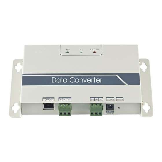
2 Overview 2.1 Instruction Fig.2.1 WAN terminal˖ Connect to the switch by 5 kinds of network cables to ensure that PC can access to the web page of it. A1B1E terminal˖ Connect to the indoor/outdoor unit A2B2E terminal˖ Connect to the terminal serial port. 2.2 System Architecture Description It supports two kinds of outdoor unit with baud rates of 600 and 4800. - Page 5 Modbus K1K2E Modbus system Fig.2.2 Connection through Modbus RTU Modbus RTU Modbus system K1K2E Fig.2.3...
-
Page 6: Usage Introduction
2.3 Function Code Function code Function Function name Read 0x01 Read Coils Read Read Input Register 0x04 Write Write Holding Register 0x10 2.4 Abnormal Reply The master unit sends requests and waits for reply from the slave. When there’s no error occurs, the slave will reply normally, but when there’s data checking error, the slave won’t answer. - Page 7 Fig.3.1 After setting, click “OK” button 3.1.2 Multi-IP Addition Configure a static IP address before adding multiple IP. Open protocol dialog and choose Advanced tab. TCP/IP setting dialog will display like below: Fig.3.2...
- Page 8 Click “Add” in IP address bar to add an IP address which is in the same segment as “192.168.1.200”, e.g., IP: 192.168.1.209ˈsubnet mask 255.255.255.0ˈand click “OK” 3.2 Configuration Input http://192.168.1.200 in the address bar in IE (suggest to use IE). Choose “Configuration”...
- Page 9 3.3 Air Conditioner Information Query Choose “power winding” or “input register” in the web page to read information of the air conditioner unit. When choose “power winding” it will be like the picture below. Fig.3.4 When click the address number of the indoor or outdoor unit, it will show correspond- ing operation information of the air conditioner.
- Page 10 Fig.3.5 The first column is the address, second is the content and the third is displayed value, e.g. 17/0011, 17 is decimal display, 0011 is hexadecimal display. Explanation of part of the content: E.g., outdoor unit on-line state: 1/0001. When No. 0 outdoor unit is on-line, its value is 1/0001(decimalism / hexadecimal ), when No.0 outdoor and No.
- Page 11 Single Air Conditioner Control Area Group control Of cooling system Fig.3.6 Single air conditioner control area: control the single air conditioner. Choose a single air conditioner and set mode, wind speed and temperature. Single control area: to choose a single air conditioner, set mode, wind speed, temperature and click “Apply”...
- Page 12 3.4 Upper Computer Access 3.4.1 Upper Computer Access Mode Upper computer system with Modbus protocol port can communicate with modbus gateway through Modbus TCP or Modbus RTU. For detailed information, please refer to Fig .2.2 and Fig. 2.3. 3.4.2 Access to Debug Via Modbus Poll software to access debugging.
- Page 13 Click “OK” when finish setting. 2˅Connection through Modbus/RTU Choose RTU to connect, as shown below: To PC port In accordance with the settings of Modbus on web page. Fig.3.9 3.4.2.3 Test Modbus Poll software can read/write the content of corresponding address in mapping table. Take reading coil content for an example: Choose “Poll Definition”...
-
Page 14: Software Reset
Take writing holding register for example: Choose button in Fig.3.7,as shown below: Change the value Modbuss Adress Registration Address of the holding After changed the value, click “send” button to finish the writing operation. 4 Software Reset Press "RESET" button on the gateway for 3 seconds and power on again, the software configuration will be back to the original setting. - Page 15 202055101005...
Need help?
Do you have a question about the CCM-18A/N-E and is the answer not in the manual?
Questions and answers