Advertisement
Available languages
Available languages
This manual is intended as a quick reference installation guide. Please refer to the control panel manufacturers installation manual for detailed
system information
GENERAL INFORMATION
The M200+ series of modules are a family of microprocessor controlled interface devices permitting the monitoring and/or control of auxiliary
devices. The M201E-240, M201E-240-KO and M201E-240-DIN are output modules, providing 250VAC 5A rated voltage free contacts, both
normally open and normally closed.
SPECIFICATIONS
Operating Voltage Range
15 to 30VDC (Min 19.5VDC to ensure LED operation - M201E-240-KO 17.5VDC)
Maximum Standby Current (µA)
275µA - No Communication
445µA - Communication LED blink enabled - 5 secs
375µA - Read 16 sec. LED blink 8 sec
Fault Current
8.8mA (Yellow LED illuminated)
Coil Activation/Deactivation Current
76mA Maximum for 12mS
Relay Contact Rating
5A, at 30VDC
5A at 250VAC
Maximum rated continuous current with the switch closed (I
Maximum rated switching current (under short circuit) (I
max)
s
Maximum leakage current (I
max) with the switch open (isolated state)
L
Maximum series impedance with the switch closed (Z
max)
c
Operating Temperature
-20°C to 60°C
Humidity
5% to 95% Relative Humidity
Dimensions M201E-240 and M201E-240-KO
134mm(H) x 139mm(W) x 40mm(D)
Dimensions M201E-240-DIN
127mm(H) x 76mm(W) x 48mm(D) (Including terminals)
Weight M201E-240 and M201E-240-KO
195g
Weight M201E-240-DIN
140g
Maximum Wire Gauge
1.5mm² - M201E-240 (KO)
2.5mm² - M201E-240-DIN
INSTALLATION
Note:
These modules must only be connected to control panels using compatible proprietary analogue addressable communication protocols
for monitoring and control.
Disconnect loop power before installing modules or sensors.
High voltages may be present on terminals 7 to 12.
M201E-240 and M201E-240 -KO
1.
The M201E-240 ( -KO ) includes a custom low profile surface-mounting box with several options for fixing centres. To access all fixing
points, and the rear cable entry knock out, the circuit board must be removed. It is held in place by two screws through the circuit board.
Ensure that these screws are replaced when refitting the circuit board.
2.
If rear cable entry is not required, the box has several cover drill points permitting the entry of cables using suitable glands.
3.
Wiring to the M201E-240 ( -KO ) is made via two 6 way terminal strips on the module circuit board, capable of supporting conductors up to
1.5mm². See figure 2 for connections.
4.
An earthing terminal is provided in the surface mount box for connection of the loop cable screen, if used, to ensure continuity. See figure 1a.
M201E-240-DIN
1.
M201E-240-DIN mounts onto standard 35mm x 7.5mm "Top Hat" DIN rail. It must be mounted in a suitable cabinet meeting the applicable
safety standards.
2.
Wiring to the M201E-240-DIN is via plug in type terminals capable of supporting conductors up to 2.5mm². See figure 2 for connections.
Ensure that the correct terminals are used for the loop and switched voltage as damage may result from incorrect usage.
For both modules, the address is selected by means of rotary decade address switches (see figure 2), accessed at the front of the module. A
screwdriver should be used to rotate the wheels to select the desired address. (Note: The number of addresses available will be dependent on
panel capability, check the panel documentation for information on this).
Short Circuit Isolators
All M200+ series modules are provided with short circuit monitoring and isolators on the intelligent loop. If required the isolators may be wired
out of the loop to facilitate the use of the modules on high current loaded loops, for example if sounders are used. To achieve this, the loop out
positive should be wired to terminal 5 rather than terminal 2.
D200-93-01
INSTALLATION INSTRUCTIONS FOR M201E-240,
M201E-240-KO AND M201E-240-DIN MAINS
SWITCHING OUTPUT MODULES
max)
1A
c
1A
15mA
130 m ohm at 15Vdc
CAUTION
WARNING
www.acornfiresecurity.com
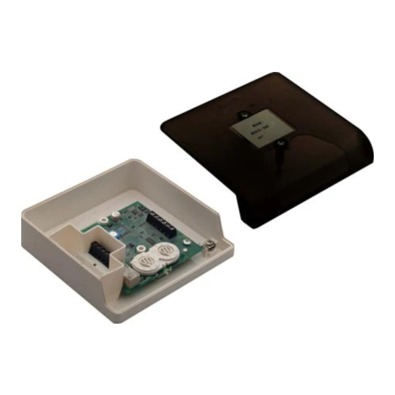
Figure 1a: M201E-240 ( -KO ) Surface Mount
Output Module with 240V Relay Contacts
Figure 2: Module Wiring.
NOTE: WIRING IS THE SAME FOR M201E-240 ( -KO ) AND M201E-240-DIN
Relay 1, N/O
Relay 2, N/C
Ground
Ground
Relay 2, N/C
Relay 1, N/O
Notes:
1.
If short circuit isolation is not required, then the loop output should be wired to terminal 5 rather than terminal 2. Terminal 5 is internally
connected directly to terminal 4.
2.
In order to meet the requirements of European Safety Standards, ensure that all cables carrying voltages in excess of 48V are suitably
fused.
1
Pittway Tecnologica S.r.l, Via Caboto 19/3, 34147 Trieste, Italy
www.acornfiresecurity.com
Figure 1b: M201E-240-DIN Din Rail Mounted
Output Module with 240V Relay Contacts.
TO MOUNT, LOCATE LUG OVER TOP OF RAIL
AND ROTATE THE MODULE DOWN TO CLIP
INTO PLACE.
TO REMOVE, PUSH UPWARDS, AND ROTATE
TOP OF MODULE AWAY FROM RAIL.
LOOP CABLE SCREEN
TERMINAL
7
1
8
2
9
3
10
4
11
5
6
12
7 8 9 10
8 9
6 7
6
11
5
5
4
12
4
3
3
13
2
2
14
1
1
0
15
0
TENS
UNITS
Rotary Decade Address Switches
Loop -, Out
Loop +, Out - See Note 1
Loop -, In
Loop +, In
Loop +, Out - See Note 1
T6 - Not Connected
0786-
CPD-20341 07
EN54-17: 2005
EN54-18: 2005
© System Sensor 2010 I56-1768-013
Advertisement
Table of Contents

Related Manuals for System Sensor M201E-240-KO


Summary of Contents for System Sensor M201E-240-KO
- Page 1 The M200+ series of modules are a family of microprocessor controlled interface devices permitting the monitoring and/or control of auxiliary devices. The M201E-240, M201E-240-KO and M201E-240-DIN are output modules, providing 250VAC 5A rated voltage free contacts, both normally open and normally closed.
- Page 2 I moduli della serie 200+ sono una famiglia di dispositivi di interfaccia controllati da un microprocessore che consentono di monitorare e/o controllare dispositivi ausiliari. I modelli M201E-240, M201E-240-KO e M201E-240-DIN sono moduli di uscita dotati di contatti liberi con tensione nominale di 250 V CA a 5A, uno normalmente aperto, l'altro normalmente chiuso.
- Page 3 La serie de módulos M200+ es una gama de dispositivos de interfaz controlados por microprocesador que permiten supervisar y/o controlar dispositivos auxiliares. El M201E-240, M201E-240-KO y el M201E-240-DIN son módulos de salida que proporcionan contactos sin tensión de 250 Vca. y 5 A, tanto normalmente abiertos como normalmente cerrados.
- Page 4 Die Module der Serie M200+ sind Mikroprozessor gesteuerte Elemente die die Überwachung und/oder Steuerung von externen Baugruppen ermöglicht. Die Module der Serie M201E-240, M201E-240-KO und M201E-240-DIN verfügen über potentialfreie Ausgänge, mit wahlweiser Schließer/Öffner Funktionalität, über die eine Netzwechselspannung von 250VAC/5A geschaltet werden kann.
Need help?
Do you have a question about the M201E-240-KO and is the answer not in the manual?
Questions and answers