Table of Contents
Advertisement
Advertisement
Table of Contents

Related Manuals for Johansson Colosseum 8500

Summary of Contents for Johansson Colosseum 8500
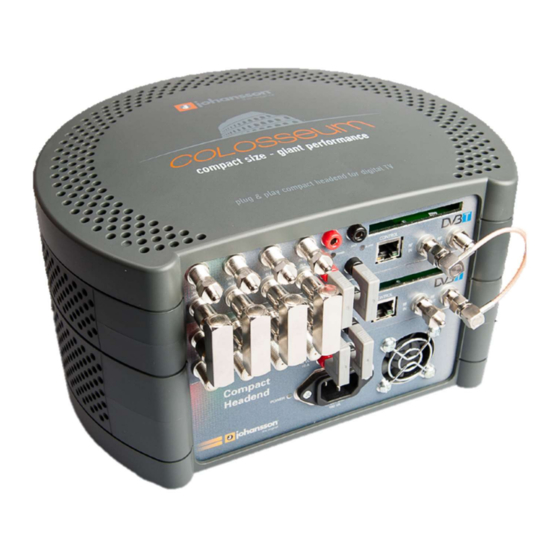
- Page 1 Colosseum user 8500 8501/8501UK manual 8505/8505UK 8506/8506UK 8550 8555...
- Page 2 Unitron cannot be held liable for any damages resulting from the use of this product. Specifications are subject to change without notice. 10/15 © Unitron - Frankrijklaan 27 - B-8970 Poperinge - Belgium T +32 57 33 33 63 F +32 57 33 45 24 email sales@johansson.be www.johansson.be - www.unitrongroup.com...
-
Page 3: Table Of Contents
CONTENTS INTRODUCTION ............................. 4 SAFETY INSTRUCTIONS ........................... 4 PACKAGE CONTENTS............................6 HARDWARE INSTALLATION ......................... 6 WEBGUI ................................8 MINIMAL SYSTEM REQUIREMENTS ........................ 8 LOGGING IN TO THE DEVICE ........................... 8 GENERAL CONFIGURATION .......................... 10 ABOUT ................................10 GLOBAL ............................... 11 FACTORY RESET ............................ -
Page 4: Introduction
INTRODUCTION SAFETY INSTRUCTIONS To prevent fire, short circuit or shock hazard: Do not expose the unit to rain or moisture. Install the unit in a dry location without infiltration or condensation of water. Do not expose it to dripping or splashing. Do not place objects filled with liquids, such as vases, on the apparatus. - Page 5 To avoid any risk of electrical shocks: Connect apparatus only to socket with protective earth connection. The mains plug shall remain readily operable. Pull out power plug to make the different connections of cables. To avoid electrical shock, do not open the housing of adapter. Only use a dry soft cloth to clean the cabinet.
-
Page 6: Package Contents
PACKAGE CONTENTS Be sure all items listed below are included: Colosseum CAT6 ethernet cable power cord user manual HARDWARE INSTALLATION The unit placed on a table (1), or mounted to the wall (2). 15 cm For wall-mounting, drill two holes, 23 cm apart and insert two screws (min length from wall to screw head is 12 mm, and diameter of screw head is max 11.5 mm). - Page 7 After positioning of the unit (wall or table), connect the cables. Connect the cables as shown in the picture: ASTRA 19.2° Vertical Low ASTRA 19.2° Horizontal Low ASTRA 19.2° Vertical High ASTRA 19.2° Horizontal High Power cord CI slots NOTES Connect the 4 cables of a Quad/Quattro LNB to prevent alarm messages.
-
Page 8: Webgui
WEBGUI MINIMAL SYSTEM REQUIREMENTS The WebGUI is supported by the following web browsers (and newer versions of these browsers): • Chrome 4 • Safari 3.1 • Firefox 3.6 • Explorer 8 • Opera 10.6 When using a different browser, we cannot guarantee a correct functioning of the interface. The webGUI will indicate this with a warning message. - Page 9 Set the adapter to obtain an automatic IP address as explained in the following procedure (for Microsoft Windows7®) Control Panel Navigate to the (Start Control Panel). Network and Sharing Center Adapter Settings Enter the and go to the Local Area Connection Properties Right-click on the and choose...
-
Page 10: General Configuration
Open your network browser, and surf to the name of the module: The name of the first module (in the middle) = MOD1 The name of the second module (on top) = MOD2 (ref.8500 & 8501/8501UK). You will now log in to the module. After logging in, the Summary window appears status ‘LED’... -
Page 11: Global
GLOBAL Here you can configure the hostname of the module. This name can be used to access the module by simply typing it into your browser as the address and surf to it. This is more convenient than using the IP address. Just enter ‘http://hostname’... -
Page 12: Firmware Upgrade
FIRMWARE UPGRADE To upgrade the firmware of the device, click the Firmware upgrade menu item BROWSE UPLOAD Click on the button, and open the upgrade file. Click to send the file to the device, this will install the new firmware on the device MODULE RESTART Press this menu item to restart the module. -
Page 13: Configuration Of The Input
CONFIGURATION OF THE INPUT Go to the LNB Settings menu to configure the 4 LNB inputs. Input: Sequence number of the input (also indicated on the front of the • actual module) • Label: custom label for each input (e.g. Vlow, or ASTRA 19.2VLow,…) •... - Page 14 TUNER Go to the menu to configure the tuner frequency. The modules have 4 independent tuners, which can be assigned to every input, thanks to a built-in multiswitch • Input: One of the 4 labels configured in the previous step. This selects the satellite input.
- Page 15 When the tuner is able to lock on the frequency, the list of services from this transponder will be shown The status of the tuner is shown. • Status: Green: tuner locked Red: tuner unlocked • Level: input signal level [dBm] •...
-
Page 16: Configuration Of The Output
CONFIGURATION OF THE OUTPUT MUX SETTINGS Navigate to the to configure the COFDM output parameters. The 4 multiplexes are adjacent, and only the frequency of the first mux needs to be configured, the others will automatically be set according to this frequency and the bandwidth. - Page 17 Ref. 8500, 8501, 8505 and 8506 • Mux: The multiplex number (1 to 4) • Frequency [kHz]: multiplex frequency in the VHF-UHF range: 47000 to 830000 kHz. When entering a frequency outside this frequency range, an error will be shown to the user •...
- Page 18 Ref. 8550 and 8555 • Mux: The multiplex number (1 to 4) • Frequency [kHz]: multiplex frequency in the VHF-UHF range: 47000 to 830000 kHz. When entering a frequency outside this frequency range, an error will be shown to the user •...
- Page 19 The TSID & LCN parameters are used to setup the logical channel numbering (channel sequence on the TV). • TSID: Transport Stream Identifier LCN: Logical Channel Number • SERVICE ASSIGNMENT Navigate to the menu to setup the TV and radio services at the output.
- Page 20 Press the button to add a new service. A list of available services (from all 4 tuners) will appear on the screen. Click on the service to be added and wait until the service is loaded into the list. The list will be refreshed and the added service will appear.
-
Page 21: Configuration Of The Mpeg Settings
CONFIGURATION OF THE MPEG SETTINGS This menu item is only visible with modules having a DVB-S 2 input. • Forward EPG tables: Forward Electronic Program Guide tables to the TV’s. • CAS forwarding: Forward the Control Access System tables (CAT, EMM, ECM) to descramble the programs with a set-top box. CAT: Conditional Access Table EMM: Entitlement Management Message ECM: Entitlement Control Message... -
Page 22: Technical Specifications
TECHNICAL SPECIFICATIONS 8500 8501/8501UK 8505/8505UK 8506/8506UK INPUT DVB-S(2) 4 satellite bands NB OF INPUTS 8 tuners (8 transponders) 4 tuners (4 transponders) TUNER 950 – 2150 MHz FREQUENCY RANGE -55 to -25dBm LEVEL 36 MHz BANDWIDTH DVB-S2: QPSK, 8PSK / DVB-S : QPSK MODULATION 0V / 13V / 18V / 22kHz / DiSEqC®... - Page 23 8550 8555 INPUT DVB-S(2) 4 satellite bands NB OF INPUTS 8 tuners (8 transponders) 4 tuners (4 transponders) TUNER 950 – 2150 MHz FREQUENCY RANGE -55 to -25dBm LEVEL 36 MHz BANDWIDTH DVB-S2: QPSK, 8PSK / DVB-S : QPSK MODULATION 0V / 13V / 18V / 22kHz / DiSEqC®...
-
Page 24: Conditions Of Warranty
CONDITIONS OF WARRANTY PERIOD OF WARRANTY Unitron N.V. warrants the product as being free from defects in material and workmanship for a period of 24 months starting from the date of production indicated on it. See note below. If during this period of warranty the product proves defective, under normal use, due to defective materials or workmanship, Unitron N.V, at its sole option, will repair or replace the product. -
Page 25: Uhf Frequency Table
UHF FREQUENCY TABLE TV band Channel Frequency MHz 470-478 478-486 486-494 494-502 502-510 510-518 518-526 526-534 534-542 542-550 550-558 558-566 566-574 574-582 582-590 590-598 598-606 606-614 614-622 622-630 630-638 638-646 646-654 654-662 662-670 670-678 678-686 686-694 694-702 702-710 710-718 718-726 726-734 734-742 742-750... -
Page 26: Power Conversion Table
POWER CONVERSION TABLE µV 75Ω µV 75Ω dBµV dBµV µV 75Ω dBµV mV 75Ω dBµV µV 75Ω dBµV -109 -109 -109 -105.5 -105.5 -105.5 63.5 -45.5 123.5 +14.5 -103 -103 -103 -101 -101 -101 -99.5 -99.5 -99.5 69.5 -39.5 129.5 +20.5 15.5 15.5... - Page 28 UNITRON NV Frankrijklaan 27 B-8970 Poperinge Belgium T +32 57 33 33 63 F +32 57 33 45 24 sales@johansson.be www.johansson.be...
Need help?
Do you have a question about the Colosseum 8500 and is the answer not in the manual?
Questions and answers