
Related Manuals for Bistos BT-300


Summary of Contents for Bistos BT-300
- Page 1 BT-300 Fetal Monitor OPERATION MANUAL BT - 300 Keep this manual for future reference P/N : 300-ENG-OPM-EUR-R09...
- Page 2 Bistos Co., Ltd. and may not be copied, reproduced, disseminated, or distributed without express written permission from Bistos Co. , Ltd. Information furnished by Bistos Co., Ltd. is believed to be accurate and reliable. However, no responsibility is assumed by Bistos Co., Ltd. for its use, or any infringements of patents or other rights of third parties that may result from its use.
-
Page 3: Table Of Contents
BT-300 Operation Manual Table of Contents 1. SAFETY ................4 1.1 Instructions for the Safe Operation and Use of the BT-300 Monitor ....4 1.2 Warnings ......................5 1.3 Cautions ......................5 1.4 General Precaution Environment ..............7 1.5 Definitions of Symbols ..................8 2. - Page 4 11.2 Ultrasound Transducer Test ................. 34 11.3 UC(TOCO) Test ................... 34 11.4 Battery Disposal and Handling ..............35 11.5 Maintenance ....................35 11.6 Disposal of the BT-300 ................35 11.7 Request a service for general problems ............35 12. Manufacturer’s Declaration..........36 P/N : 300-ENG-OPM-EUR-R09 Bistos Co.,Ltd.
-
Page 5: Safety
The recommended testing interval is once per year. Do not operate the BT-300 monitor if it fails to pass the power on self- test procedure. WARNING: Be informed that it may cause serious injury or death to the patient, property damage, and material losses against the “Warning”... -
Page 6: Warnings
This can cause the electric shock to the patient or operator. WARNING: SHOCK HAZARD — During upgrading the BT-300, do not use the BT-300 to the patient. This can cause the electric shock to the patient. Cautions... - Page 7 CAUTION: When the printer door is open, do not put the finger to the inside of BT-300. This can cause the finger wound. Also do not prick the inside of BT-300 when the printer door is open. This can cause the damage to the device or electric shock.
-
Page 8: General Precaution Environment
Do not disjoint or Power off when disassemble the the equipment is equipment. not fully installed. BISTOS Co., Ltd. Otherwise, the does not take equipment could responsibility of it. be damaged. P/N : 300-ENG-OPM-EUR-R09 Bistos Co.,Ltd. 2018,03... -
Page 9: Definitions Of Symbols
BT-300 Operation Manual Definitions and Symbols Symbol Description Power On/Off Button This symbol identifies a safety note. Ensure you understand the function of this control before using it. There are no noted or identified hazards by ultrasound. But there is unknown hazardous possibility by ultrasound. -
Page 10: Introduction
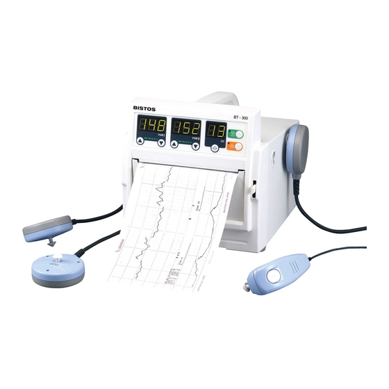
BT-300 Operation Manual Section Introduction General This chapter provides a general description of the BT-300 monitor including: Brief Device Description Product Features Model Configurations Brief Device Description The BT-300 is a microprocessor-based fetal monitor, providing continuous monitoring, display, and recording of fetal heart rate (FHR) and uterine contraction (UC) for antepartum testing and monitoring. -
Page 11: Options And Accessories
Adaptor for transform AC Power Power Adaptor (100-240V ~) to DC 18V(2.5A) Type / model : 18650 LI-ION Battery Technical data : 3.7V * 4ea, 2600mA Ultrasound transmission gel Ultrasound Gel (Sanipia, ECOSONIC) Table 2.1. BT-300 Accessories P/N : 300-ENG-OPM-EUR-R09 Bistos Co.,Ltd. 2018,03... -
Page 12: Installation
BT-300 Operation Manual Section Installation Description of the BT-300 Front Panel ⑨ ⑪ ⑥ ⑫ ⑦ ⑬ ⑧ ⑩ ⑭ ③ ② ⑤ ① ④ Fig. 3.1 BT-300 Front Panel ① (AC:Green / Battery:Orange) Power Indicating LED ② DOP 1 Connector ③... -
Page 13: Description Of The Left Panel
BT-300 Operation Manual Description of the Left Panel ② ① Fig. 3.2 BT-300 Left Panel ① DOP 1 Probe Holder ② DOP 2 Probe Holder(AST Probe Holder) Description of the Right Panel ① ② Fig. 3.3 BT-300 Right Panel ①... -
Page 14: Descriptoin Of The Rear Panel
Speaker Power On When the user wants to turn BT-300 on, power adaptor is connected with power adaptor jack connector on Rear panel of BT-300 as shown in Figure 3.4 and power button is pressed. Patient Cables The ultrasound and TOCO transducer cable are connected to the front panel. -
Page 15: Event Marker Cable
BT-300 Operation Manual Event Marker Cable The event marker cable is connected to the connector in the front panel. The label on the housing shows the location of the connector. The cable is connected by putting into the connector tightly. There is no connector locking mechanism. -
Page 16: Bt-300 Operation
BT-300 Operation Manual Section BT-300 Operation System Startup 4.1.1 Configuration Settings The monitor has several configuration settings that the user can change. Some of these settings are reset to the default value each time the monitor is powered down. Other parameter settings are saved in the monitor until the next time they are changed. - Page 17 74 ~ 200 bpm range. 4.1.2 Understanding and Setting Alarms The BT-300 monitor has the capability to alert the caregiver in the event a heart rate goes above or below an alarm limit for a preset time delay. P/N : 300-ENG-OPM-EUR-R09 Bistos Co.,Ltd.
-
Page 18: Understanding And Setting Alarms
BT-300 Operation Manual The limit values are configurable. These limit values have no significant meaning in clinical uses. To prevent overwrapping of limit value, there is an apartness of upper or lower limit by 5 bpm. The purpose of setting for the limit values is to give accommodation to user. -
Page 19: Setting Time And Date
Date {1 ~ 31 Date} Hour {0 ~ 23 Hour} Minute {0 ~ 59 Minute} Second {0 ~ 59 Second} To save and exit setup menu. ]Button Press BT-300 Monitor Display Screen Print Alarm UC Frame FHRⅠFrame FHRⅡFrame Fig. 4.3 FHR & UC value display panel... -
Page 20: Uc Frame(Toco Numeric Frame)
DOP1 is not connected while BT-300 is monitoring DOP2 is not connected while BT-300 is monitoring Print door is opened while BT-300 is printing Paper is not loaded while BT-300 is printing Battery’s charging level is low while BT-300 is monitoring BT-300 Monitor Controls and Indicators There are seven buttons located on the front panel. -
Page 21: Recorder Operation
BT-300 Operation Manual Section Recorder Operation Loading Paper The paper is loaded by pulling down the lever to open the door. Unwrap a pack of paper and put it into the paper tray. Several pages from the top of the pack of paper should drape forward over the shaft of the recorder. - Page 22 BT-300 Operation Manual The printer LED in on when the paper is loaded correctly and the printer is operating. The printer LED is off when the printer is off. If there is no paper, “no paper” alarm will be displayed and alarm sounds.
-
Page 23: Monitring Fetal Heart Rate
Move all line cords and line-powered equipment at least 6 feet away from the BT-300. Check for extension cords running behind or under the bed and equipment in adjacent rooms. If the artifact heart rate indication ceases, the monitor may be used normally. - Page 24 BT-300 Operation Manual Determine whether the monitor is powered from the internal battery or the AC power. If operating on the internal battery, check the battery status to determine whether the battery has sufficient charge to complete the monitoring session. Use the AC power if the “low battery”...
-
Page 25: Detail Procedure
BT-300 Operation Manual Step 4: Monitor Adjustments Readjust the volume settings for the desired loudness. Detail Procedure ① Explain procedure to the patient. ② Place a probe belt under the patient. ③ Turn the monitor power on. The power switch is located on the rear panel. - Page 26 BT-300 Operation Manual ⑪ If the printer is not already activated, press the [ ] button located on the front panel of the monitor. The recorder plots the FHR on the paper strip chart. Figure 6.2 Positioning of UC Probe P/N : 300-ENG-OPM-EUR-R09 Bistos Co.,Ltd.
-
Page 27: Uterine Contraction(Uc)
Uterine contraction is measured externally by placing a pressure sensitive device (Tocotonometer) on the maternal abdomen and recording relative pressure changes. CAUTION: During the using BT-300, we do not intend that the cable of UC sensor contacts to the patient. To prevent that the cable contacts to the patient, please cover the patient’s abdomen section which have a... - Page 28 BT-300 Operation Manual ③ Turn the monitor power on. The power switch is located on the rear panel. The green indicator located under the left side of the printer door illuminates when the power on. ④ Connect the transducer plug to “UC” connector located on the underside of the front cover.
-
Page 29: Event Marker
BT-300 Operation Manual Section Event Marker Event Marker The event marker arrow is provided so that the patient can record the time of important events. The patient merely presses the marker button located on the end of the marker cable at the time an event occurs. The event marker icon by patient’s press is an upward pointing arrow. -
Page 30: Cleaning And Disinfection
Operation Manual Section Cleaning and Disinfection This chapter contains instructions for the care and cleaning of the BT-300 unit and its accessories. The BT-300 requires proper care and preventive maintenance. This ensures consistent operation and maintains the high level of performance necessary in monitoring procedures. -
Page 31: Belts
BT-300 Operation Manual residue. 6. Dry the device thoroughly with a sterile soft towel or gauze surgical sponge. 7. Wrap the dry device in a fresh sterile soft towel or transparent sterile wrap for storage until next use. Belts Wash soiled belts with soap and water. -
Page 32: Specifications
BT-300 Operation Manual Section Specifications BT-300 Monitor Specifications: Physical Characteristics Dimensions – 19.1 cm H x 18.7 cm W x 20.1 cm D Weight - approx. 5.0 kg Safety Complies with IEC 60601-1, IEC 60601-1-2, IEC 60601-2-37 Class I Equipment & Internal Powered Equipment... - Page 33 BT-300 Operation Manual Accuracy: ±1% relative unit Leakage: <10 µA @ 264 VAC applied to transducer Isolation: >4 kV RMS, Type BF applied part Paper Pack Style: Z-Fold. Pack Size: 130 mm x 120 mm x 20 mm End-of-Pack: Mark along paper edge...
- Page 34 BT-300 Operation Manual Acoustic Output Reporting Non-Auto scanning Mode Operating Mode : PW Mode Acoustic SPTA.3 SPPA.3 Output (mW/cm (mW/cm Global Maximum Value 0.04 17.6 0.396 (MPa) 0.063685 (mW) 16.7* 16.7* (MHz) 0.985 0.985 0.985 (cm) Associated Beam (cm) Acoustic...
-
Page 35: Troubleshooting And Maintenance
BT-300 Operation Manual Section Troubleshooting and Maintenance 11.1 User Test The user has to check the monitor performances each time the unit is turned on. 1. Make sure the monitor power is properly connected. 2. Check the recorder for paper and door open. -
Page 36: Battery Disposal And Handling
When disposing of the BT-300, adhere to all applicable laws regarding recycling. If you are not able to dispose the BT-300 or you need a help for disposing the BT-300, please contact us. In the case of there are no appropriate ways to dispose, we will pick up the BT-300 for you. -
Page 37: Manufacturer's Declaration
Section Manufacturer’s Declaration 12.1 Electromagnetic emissions The BT-300 is intended for use in the electromagnetic environment specified below. The customer of the user of the BT-300 should assure that it is used in such an environment. Emission test Compliance Electromagnetic environment - guidance... - Page 38 BT-300 Operation Manual 12.3 Recommended separation distances between portable and mobile RF communications equipment and the BT-300 Rated Separation distance according to frequency of transmitter [m] maximum 150 kHz to 80 MHz 80 MHz to 800 800 MHz to 2.5...
- Page 39 If the measured field strength in the location in which the BT-300 is used exceeds the applicable RF compliance level above, the BT-300 should be observed to verify normal operation. If abnormal performance is observed, additional measures may be necessary, such as re-orienting or relocating the BT-300.
- Page 40 Sales Agency Manufacture Bistos Co., Ltd ※ Thank you for purchasing BT-300. ※ This product is manufactured and passed through strict quality control and inspection. ※ Compensation standard concerning repair, replacement, refund of the product complies with “Consumer’s protection law” noticed by Economic Planning Dept.
Need help?
Do you have a question about the BT-300 and is the answer not in the manual?
Questions and answers