Veeder-Root EMR4 Setup And Operation Manual
Measuring and monitoring relays
Hide thumbs
Also See for EMR4:
- Technical installation manual (39 pages) ,
- Pc setup quick help manual (2 pages) ,
- Application manual (71 pages)
Table of Contents
Advertisement
Advertisement
Table of Contents

Related Manuals for Veeder-Root EMR4


Summary of Contents for Veeder-Root EMR4
- Page 1 ● Manual No: 577014-350 Revision: A EMR4 Setup and Operation Manual...
- Page 2 Customer Service will work with production facility to have the replacement product shipped as soon as possible. If “lost” equipment is delivered at a later date and is not needed, Veeder-Root will allow a Return to Stock without a restocking fee.
-
Page 3: Table Of Contents
Display Button Functions - Optional Keypad ..............7 Data Entry Navigation Buttons ......................8 Data Entry with Standard Keypad ..................8 Data Entry with Optional Keypad ..................9 EMR4 Operating States and Modes System Operating States ....................10 Pre-Dispense State ....................10 Dispense State .......................10 Finish State......................10 System Operating Modes ....................10... - Page 4 Table of Contents System Address .....................27 Time Delays......................29 Version Number......................30 C&C Mode Initiating the C&C Mode ....................31 C&C Mode Setup Categories ..................31 Language........................32 Display Syntax......................35 Temperature ......................36 Fuel Source ......................37 Temperature Compensation Method - Coefficient of Expansion......40 Temperature Compensation Method - Density Ratios for Liquified Petroleum Products ....................43 Meter Calibration ....................44 Configure I/O ......................47...
- Page 5 E64 - Fuel Type Undefined..................67 E65 - Calibration Error....................67 Other Problems .......................68 System Boots Up Okay, but Display Keys Don’t Respond........68 Appendix A: EMR4 Setup - Programming Tips Appendix B: Epson Printer Characters Appendix C: External Sources of System Noise Figures Figure 1.
- Page 6 Security Code ..................53 Figure 54. IB Tri-Color LED Status Flash Patterns ..........66 Tables Table 1 - EMR4 Default Syntaxes ................35 Table 2 - Product Temperature/Coefficient of Expansion Defaults ......40 Table 3 - Temperature/Coefficient of Expansion Defaults for Propane1 ....40 Table 4 - Minimum &...
-
Page 7: System Features
System Setup There are two distinct categories of EMR4 setup; Setup Mode which can be accessed at any time by the equipment operator, and C&C (Configuration and Calibration) Mode which is only to be entered in accordance with Weights and Measures (W&M) requirements. -
Page 8: C&C Mode
The C&C Mode setups must be performed before you make selections in the non-metrological controlled Setup Mode - There is one exception: When initially powering up an EMR4 System with two Display Heads, System Address Setup (in Setup Mode) must be completed before entering C&C Mode (see page 27 to page 29). -
Page 9: Safety Symbols
Introduction Safety Symbols Safety Symbols The following safety symbols are used in this manual to alert you to important safety hazards and precautions. EXPLOSIVE FLAMMABLE Fuels and their vapors are extremely explo- Fuels and their vapors are extremely flam- sive if ignited. mable. -
Page 10: Display Head
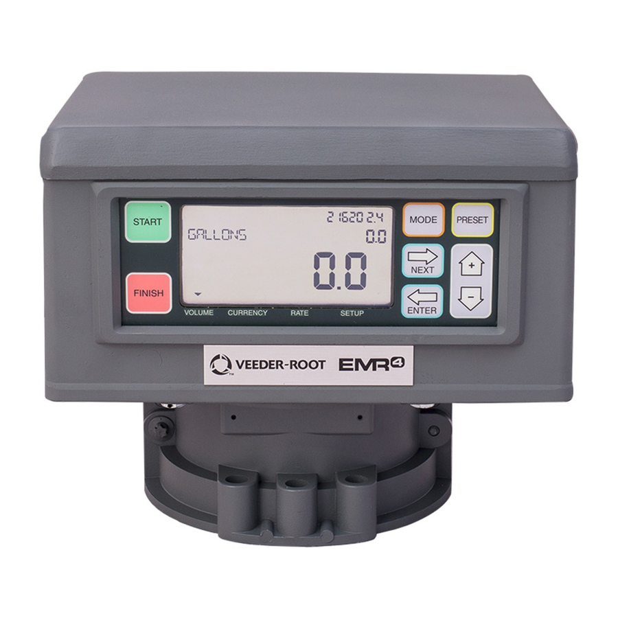
Introduction Display Head Display Head The EMR4 Display Head display features are shown in Figure 1 and Figure 2. Grand Totalizer Field Preset Indicator Operating Icons Preset Field Descriptor Field VEEDER ROOT CO Register Field Temperature Icon Mode Indicator Standard Keypad Figure 1. -
Page 11: Boot-Up Test Sequence
Version number On initial startup of EMR4 Systems with two Display Heads, you must go to the Head Address Setup (Figure 27 on page 28) and assign an unique Head Address for each Display Head. Because the factory default Head Address is set to a “1”, one of the two Display Head’s addresses must be changed to a “2”. -
Page 12: Activating The Display
Introduction Activating the Display Activating the Display OEM MESSAGE DISABLED Display is blank after the 30 second timeout. Press a button on the display, if the timeout follows setup, the pre- dispense default mode is displayed. Otherwise the display on the screen prior to the timeout will display. OEM MESSAGE ENABLED Display is blank after 30 second timeout. -
Page 13: Display Button Functions - Standard Keypad
Introduction Display Button Functions - Standard Keypad • Preset Indicator - An indicator icon will point to the Preset Field to indicate the Status of the Preset when in that mode, otherwise it will not appear. It will flash when the Preset is set but disabled and will remain solid when the Preset is enabled. -
Page 14: Data Entry
Data Entry Navigation Buttons The navigation buttons consist of the MODE, NEXT, ENTER, PRESET, and +/- buttons. They can be used to either select and set parameters, or select and set alpha and numeric values. • MODE - Press to navigate through the Modes; Setup, Volume, Currency, and Rate. •... -
Page 15: Data Entry With Optional Keypad
Data Entry Data Entry with Optional Keypad Data Entry with Optional Keypad Upon entering the Descriptor or Preset Field with the use of the navigation buttons the optional keypad will permit alpha and numeric entries. To enter a numeric character in the Preset Field just select the appropriate button on the optional keypad. When a selection is made, the cursor will automatically sequence to the position to the right. -
Page 16: Emr4 Operating States And Modes
System Operating Modes Four operating modes are used in the EMR4 System. They are Volume, Currency, Rate, and Setup. These modes can be navigated by use of the MODE button. In Setup, the default Mode for Pre-Dispense and Dispense states can be set. -
Page 17: Setup Mode
CALIBRATION AND CONFIGURATION (C&C) MODE The C&C Mode is entered by a trained technician following instructions in the EMR4 Application Guide (V-R P/N 577014-339). When the display head is powered up after the C&C Mode is enabled, the C&C related parameters of the Setup Mode are displayed. -
Page 18: Setup Mode
Time/Date setup - lets you enter the current time and date (see page 27). • System Address setup - sets the addressing and configuration of the individual EMR4 components and their inputs from, and outputs to, the system (see page 27). -
Page 19: Enter Security Code
Setup Mode Setup Mode Categories ENTER SECURITY CODE NOTE: These menus do not appear until the SECURITY CODE feature is enabled in the C&C mode, described in Figure 51 of this manual. Figure 6 illustrates the initial logging in procedure using the default Passcode after Security Codes are enabled in C&C Mode (see Figure 51). -
Page 20: Pricing
Setup Mode Setup Mode Categories PRICING Figure 9 illustrates Pricing setup in Setup Mode. Note: if user isn’t logged in, the price cannot be changed. Press up/down PRICE CODE 1 PRICING to change digit CHANGE PRICE X PRICE X Press to accept and NEXT to ASSIGN TAX/DIS choice... -
Page 21: Tax/Discount
Setup Mode Setup Mode Categories TAX/DISCOUNT Figure 10 illustrates Tax/Discount setup in Setup Mode. The Subtotal feature allows you to define and insert additional subtotal lines in the same manner as the existing tax or discount lines. Adding this feature creates a type called subtotal (T/D/S). Type subtotal is a selection in the CHNG T/D VALUE menu that has no user defined value, but does have the ASSIGN TO LINE selection. -
Page 22: Defaults
Setup Mode Setup Mode Categories Figure 11 illustrates Defaults setup in Setup Mode. + START MODE Go To Figure 12 DEFAULTS PRESETS Go To Figure 13 DELIVERY REPORT Go To Figure 14 RELAY CONTROL AUTHORIZATION SECURITY PRINTER OPTION Authorization is required for all deliveries VIEW RECORDS and serial access to custom fields is RESTORE RECORD... - Page 23 Setup Mode Setup Mode Categories Presets Figure 13 illustrates delivery Presets setup in Setup Mode. The PRESET ENABLE menu is associated with the PRESET INTERLOCK description and the BATCH ENABLE menu is associated with the TRANSFER INTERLOCK description. Interlock switches are not provided by Veeder- Root and are not required when using presets.
- Page 24 Setup Mode Setup Mode Categories Delivery Report Figure 14 illustrates printing out the End of Day Delivery Report. RETURN TO DEFAULTS FIGURE 11 START MODES PRESETS Prints the end of day TODAY’S DELIVERIES DELIVERY REPORTS Delivery report (see format below) SUMMARY PRINTOUT Deliveries Made - Feb-03-2011...
-
Page 25: Relay Control
Setup Mode Categories RELAY CONTROL The EMR4 must be in Preset Mode to control the flow valve solenoid(s). For a single-stage flow valve, use Relay 2 (Stop), for a dual-stage flow valve, use Relay 1 (Slow) and Relay 2 (Stop). -
Page 26: Security
Setup Mode Setup Mode Categories SECURITY NOTE: These menus do not appear until the SECURITY CODE feature is enabled in the C&C mode, described in Figure 51 of this manual. Figure 16 illustrates the procedure for setting user pass codes and user access to certain setup parameters. SECURITY USER 1 CHANGE CODE... -
Page 27: Printer Option
Setup Mode Setup Mode Categories PRINTER OPTION Figure 17 illustrates Printer Option setup in Setup Mode. This option lets you select a printer type and make the appropriate settings. SLIP PRINTER PRINTER OPTION ENABLE PRINTER ADVANCE ROLL PRINTER DISABLE PRINTER PRINT TEST PAGE THERMAL PRINTER PRINT CALIB PAGE... - Page 28 Setup Mode Setup Mode Categories V e e d e r - R o o t C o . Header E M R - 4 (Up to 4 lines) Optional S T A R T M M M - D D - Y Y Y Y H H : M M : S S Date/time F I N I S H M M M - D D - Y Y Y Y H H : M M : S S...
-
Page 29: View Records
Setup Mode Setup Mode Categories VIEW RECORDS Figure 19 illustrates View Records setup in Setup Mode. RECORD 1 VIEW RECORDS VIEW LINES PRINT RECORD RECORD 50 Note: View each line or print Note: Up to the last 50 transaction records the selected report. -
Page 30: Restore Records
Setup Mode Setup Mode Categories RESTORE RECORDS Figure 20 illustrates Restore Records procedure in Setup Mode. RESTORE RECORDS DECLINE ACCEPT RESTORING TRANSCTION 50, 49, ... 1 Note: Last 50 Transactions are being Press the up/down restored. Counts down from 50 to 1 buttons to cycle (number of stored transactions may through remaining... -
Page 31: Shift
Setup Mode Setup Mode Categories SHIFT Figure 21 illustrates Shift setup and the Shift Report printing procedure in the Setup Mode. Figure 22 illustrates the format of a shift report. When a shift report is selected, a separate report will be printed for each product if transactions for that product were recorded in the selected shift. -
Page 32: Date Format
Setup Mode Setup Mode Categories Report Line Item Source SHIFT BEGIN: Starting time/date of the shift SHIFT END: Ending time/date of the shift (only displayed if shift has ended ) PROD DSCRPT: Name assigned to the product (e.g., gasoline) METER ID: Meter ID number assigned to the unit BEGINNING VOLUME: Total volume at the beginning of the shift (= ending volume of last shift) -
Page 33: Time/Date
Setup Mode Setup Mode Categories TIME/DATE Figure 24 illustrates Time/Date setup in Setup Mode. Press up/down arrows to scroll through the choices, and NEXT to move from one MMM DD HH:MM:SS YYYY group of the date, time, or year to another. - Page 34 Setup Mode Setup Mode Categories IB Address Setup Figure 26 illustrates the IB Address setup selections (the default IB address is 1). This setup is necessary only when there are more than one IBs connected in a network. Press ENTER to return to SYSTEM ADDRESS SET IB ADDRESS 1 IB ADDRESS*...
-
Page 35: Time Delays
Setup Mode Setup Mode Categories Printer Address Figure 28 illustrates Printer Address setup choices. Press ENTER to return to SYSTEM ADDRESS PRINTER ADDRESS LOCAL PRINTER SET PRINTER 1 SET PRINTER 16 This menu selects the printer for this Display Head. Select a printer on Host IB (the IB to which this Display Head is wired), use Local Printer. -
Page 36: Version Number
Setup Mode Setup Mode Categories VERSION NUMBER Figure 30 illustrates Version Number viewer in Setup Mode. VERSION NUMBER HEAD NUMBER 349870-00X HEAD BOOT NUMBER IB NUMBER Displays the software version IB BOOT NUMBER of the Display Head Press the up/down buttons to cycle through remaining Setup Mode categories... -
Page 37: C&C Mode
C&C Mode Initiating the C&C Mode NOTE: To access C&C Mode you must first configure the display head as instructed in the EMR4 Application Guide (V-R P/N 577014-339). 1. Press MODE button until the indicator at the bottom of the display points to SETUP. -
Page 38: Language
C&C Mode C&C Mode Setup Categories IMPORTANT! If in a C&C Setup you press ENTER too many times, you may ‘back’ out of the C&C Mode and end up somewhere in the Setup Mode menu. To reenter C&C Mode, scroll around as shown below: SETUP MODE CATEGORIES C&C MODE CATEGORIES ENTER SECURITY CODE... - Page 39 TOTAL TAX/DISCOUNT 4 AVG FLOW RATE GPM TOTAL TAX/DISCOUNT 5 PRICE/GALLON TOTAL TAX/DISCOUNT 6 FINAL PRICE/GALLON Veeder-Root Co. SUBTOTAL Note: Any or all of these four lines EMR-4 PRICE INCLUDING TAX can be used for the header at the "blank"...
- Page 40 C&C Mode C&C Mode Setup Categories Designations in Printed Tax & Group software of Discount Labels Code Adjacent Labels Tax and Discount labels automatically print in 2 or 3 line TAX_PERCENT1 TAX T/D groups. The (A1, B1, etc.) to the left of the software desig- TAX_PER_VOLUME1 UNIT TAX T/D nations indicate the label's group and line position (e.g.
-
Page 41: Display Syntax
C&C Mode C&C Mode Setup Categories DISPLAY SYNTAX Figure 34 illustrates Display Syntax setup in C&C Mode. Table 1 shows the EMR4 display syntax defaults. Press ENTER to accept DECIMAL SYMBOL 8888.88 SELECT DEC SYM choice 8888,88 88888.8 Press ENTER to accept... -
Page 42: Temperature
C&C Mode C&C Mode Setup Categories TEMPERATURE Figure 35 illustrates Temperature Probe’s setup in C&C Mode. Press ENTER to accept any changes in any column - and/or continue pressing to return to TEMPERATURE GO TO TEMPERATURE TEMPERATURE FAHRENHEIT CALIBRATION SETUP CELSIUS (FIGURE 36) Press the up/down... -
Page 43: Fuel Source
C&C Mode C&C Mode Setup Categories FUEL SOURCE Figure 37 illustrates Fuel Source setup in C&C Mode. If you are going to make temperature compensated deliveries, before performing Fuel Source setup, you must select either coefficient (of expansion) or density as the temperature compensation method in Delivery Options setup (see Figure 47). - Page 44 Entering a Custom Name for a Product Type There are eight default Product Types in the EMR4. If you select one of the default Product Types you do not have to accept a default Product Name. For example, if you wanted to assign Jet Fuel to Product 1, select Jet A as the...
- Page 45 C&C Mode C&C Mode Setup Categories After assigning a Product Type or a Cal Number to any Product Description number, the meter must be recalibrated in Meter Calibration Setup. RETURN TO FUEL SOURCE FIGURE 37 PRODUCT NAME PROD DSCRPT 1 TEMPERATURE COMPENSATION* PRODUCT DSCRIP CAL NUMBER...
-
Page 46: Temperature Compensation Method - Coefficient Of Expansion
C&C Mode C&C Mode Setup Categories TEMPERATURE COMPENSATION METHOD - COEFFICIENT OF EXPANSION Table 2 - Product Temperature/Coefficient of Expansion Defaults Product Coefficient °C Coefficient °F Default Density at 15°C OIML R63 Table Gasoline 0.00126 0.00070 737 kg/m Diesel 0.00081 0.00045 849 kg/m Jet A... - Page 47 C&C Mode C&C Mode Setup Categories TEMPERATURE COMPENSATION METHOD - DENSITY RATIOS FOR LIQUID PETROLEUM PRODUCTS Table 4 - Minimum & Maximum Product Densities at 15°C EMR4 Canadian Min. Density Max. Density Default Density Default Density OIML R63 Product (kg/m...
- Page 48 15°C (e.g., change from 60°F to 15°C) 3. In order to change the density for a given product, the EMR4 has to be set to the density mode and temperature compensation must be enabled as described in Figure 47, Delivery Options. ...
-
Page 49: Temperature Compensation Method - Density Ratios For Liquified Petroleum Products
469.0 555.0 For other liquefied gases modify the density defaults to their proper values in accordance with ASTM-IP Tables. The EMR4 calculates temperature compensated volume using the 12 density pairs from Table 5 above in the following formula: / ... -
Page 50: Meter Calibration
C&C Mode C&C Mode Setup Categories METER CALIBRATION Figure 41 illustrates Meter Calibration setup in C&C Mode. Press ENTER to accept any changes in any column - and/or continue pressing to return to METER CALIBRTN See Meter PROD CAL 1 Calibration METER CALIBRTN AUTO CALIBRATE... - Page 51 C&C Mode C&C Mode Setup Categories MultiCalibrate Figure 43 illustrates meter MultiCalibration setup procedure. RETURN TO PROD CAL 1 (FIGURE 41) CALB RATE 1 MULTICALIBRATE START DISPENSE Note: In this multipoint calibration option you dispense at CALB RATE 8 up to 8 different flow rates. These rates are determined by how much you squeeze the nozzle handle during each calibration.
- Page 52 C&C Mode C&C Mode Setup Categories Manual Calibration Figure 44 illustrates meter Manual Calibration (multipoint) setup procedure. This method requires the meter manufacturer’s meter error chart. Repeat this procedure until RETURN TO you have entered a corrected PROD CAL 1 encoder count from the table (FIGURE 41) for each of your flow rates.
-
Page 53: Configure I/O
C&C Mode C&C Mode Setup Categories CONFIGURE I/O Figure 45 illustrates Configure I/O setup in C&C Mode. DISABLE ENABLE For Emergency Stop switch only. CONFIGURE I/O EMERGENCY STOP Not for Remote start/stop. REM START/STOP REMOTE DISPLAY NORMALLY OPEN INTERLOCK NORMALLY CLOSE NOTES: EMERGENCY STOP (ES) - Once an ES Normally Open is enabled, a switch closure between Press the up/down... -
Page 54: Delivery Options
DISABLE CUSTOM FIELD 7 PRICE CHANGING TEMP COMPENSATION DELIVERY TIMEOUT TANK ID/PIN CTRL The actual EMR4 Delivery Option CUSTOM FIELDS sequence is shown at right. The E04 ENCODER PULSE ERROR sequence shown in the diagram GROSS VOLUME TEMPERATURE ON TICKET... -
Page 55: Report Formats
Two Idle State safety features (Stop Flow Timeouts) are built into the EMR4 system. • Pressing the START button puts the EMR4 into the Delivery State. If fuel flow is not detected within 1200 seconds (default), the delivery is terminated. The nozzle icon (Figure 1 on page 4) will begin blinking 30 seconds before delivery is terminated. - Page 56 Shift Report (Example) FUEL SOURCE Line 1 ADVANCE Line 1 ADVANCE METER CALIBRTN Top of ticket Line 2 Top of Report Veeder-Root Co. Line 2 ************************** CONFIGURE I/O Line 3 EMR-4 Line 3 Veeder-Root Co. OEM MESSAGE Line 4 (blank)
- Page 57 Line 1 END OF REPORT Example 3 - Inserting a line Line 2 Example 1 - Switching 2 lines Veeder-Root Co. Line 3 EMR-3 IMPORTANT! If you want to insert a line you Supose you want to modify the example...
-
Page 58: Restart
C&C Mode C&C Mode Setup Categories RESTART Figure 50 illustrates the Restart procedure in C&C Mode. CAUTION: DO NOT USE UNDER NORMAL CONDITIONS! RESTART PRESERVE NVRAM INIT NVRAM SOFTWARE UPGRADE Selecting YES, then ENTER reboots and Press the up/down performs a self-test of the Display Head, buttons to cycle without changing any setup parameters through remaining... -
Page 59: Security Code
Figure 7 on page 13. Exiting C&C Mode 1. Turn Off power to the Display Head. Disable the C&C Mode by replacing C&C jumper, etc., (see EMR4 Application Guide, V-R P/N 577014-339). 2. Replace cover on Display Head. -
Page 60: Operation Of The System
Multiple Products The EMR4 is capable of delivering multiple products through the same meter. If more than one product is set up in the setup menu, when the START button is depressed, the multiple product selection is initiated and the first product is displayed. -
Page 61: Entry Of Price Codes & Tax/Discount Assignment In Setup Mode
Preset Operation and Tank Topping The Preset operates in a specific manner in the EMR4. Whether the display is set in Volume or Currency Mode, the Preset is actually counting volume in the background. This is to say changing the value of the preset in Currency Mode, in currency, changes the equivalent volume preset level in the background. -
Page 62: Viewing Tank Load During A Delivery
Operation of the System Viewing Tank Load During a Delivery control relay 1 opens and the register displays a slower dispense rate. When the amount dispensed then reaches the designated stop point, flow control relay 2 opens and shuts off flow at the delivery’s preset value. The user can disable the preset during the operation of the unit by pressing the PRESET button to go to the Preset Countdown, selecting disable, and pressing the ENTER Button. -
Page 63: Typical Dispensing Examples
Operation of the System Typical Dispensing Examples 1. Operator selects the price of $2.00 for the delivery and presses ENTER to accept (no Preset Icon displayed). 2. Presses PRESET button to display the Preset countdown value (No Preset Icon displayed). 3. -
Page 64: Dispensing Volume Without Price But With Preset Before Dispensing
Operation of the System Typical Dispensing Examples DISPENSING VOLUME WITHOUT PRICE BUT WITH PRESET BEFORE DISPENSING 1. In Volume Mode, press START button. 2. Press PRESET to go to the Preset screen. Press NEXT button to go to Change Preset screen, increment up or down to desired default preset, then press Enter to accept. -
Page 65: Dispensing Currency With Price Code Before & Currency Preset After Dispensing
Operation of the System Typical Dispensing Examples 4. Press NEXT button to Change Preset, select the default preset desired then press ENTER button to accept the value. (If the user wishes to alter the preset they press NEXT again to Enter Preset screen. Using the NEXT button, +/- buttons, followed by ENTER button, the new preset value is achieved and the new preset is displayed. -
Page 66: Dispensing Currency With Price Code & Volume Preset After Dispensing
Operation of the System Typical Dispensing Examples 7. Press START to begin delivery (if Display Head is configured for more than one product, you must select a product first). The Product Description + the Price Unit are displayed in the Description Field, the net price in the Preset Field, and the Total Dispense Value so far is displayed in the Register field. -
Page 67: Dispensing With Batch Preset By Product Enabled
Operation of the System Typical Dispensing Examples 16 characters). Press ENTER when you have entered the desired label. Note, if you were to press ENTER when CUSTOM FIELDS displays, the message CUSTOM FIELDS NOT ENTERED will scroll across the Descriptor Field. To avoid seeing this message, you have to press NEXT after CUSTOM FIELDS is displayed. For single or multiple deliveries, the first three Custom Fields will be used for operator entries at the start of a delivery. -
Page 68: Dispensing With Multiple Deliveries Disabled
1. In Setup Mode - Delivery options menu Disable Multiple Delivery. 2. In Volume Mode, press START button to initiate delivery (though START button is pressed for longer time EMR4 will not go in to Multiple Delivery mode). 3. Deliver Product until required Volume level is reached. -
Page 69: Emr4 Troubleshooting Guide
Most errors are the result of poor terminations of wiring, either in a junction box, or at the terminal strips in the IB box or Display Head. Note: The EMR4 encoder is a 2-channel quadrature pulse output device in which the A-channel leads the B- channel by 90 degrees in order to create 4 unique states. -
Page 70: New Calibration Required
After assigning a Product Type or a Cal Number to any Product Description number, this message alerts the user to recalibrate the meter in the Meter Calibration Setup. If the user does not recalibrate the meter, the EMR4 will use an incorrect meter calibration factor to calculate volume. -
Page 71: System Error Codes
Head Address. Put the Display Head in Set-up Mode and go to the System Address menu to check the address number for each display head. Cycle the power to EMR4 system to clear the error message once an address change is made. -
Page 72: E66 - Printer Busy
EMR4 Troubleshooting Guide System Error Codes Flash Sequence Where: FG= Flash Green, FR=Flash Red, FY=Flash Yellow, P=Pause off Repeats Power On Sequence 1 Display Head Communicating Repeats 2 Display Heads Communicating Repeats Repeats until 1 Or More IB Relays Are Active... -
Page 73: Exc Error
Off and On before replacing the Display Head. ERROR Error – Indicates a CPU processing error associated with embedded software used by the EMR4 system. Try cycling power to the IB Box before initializing NVRAM and reprogramming the Display Head. Note that this Error may appear in either the Register Field or the Grand Totalizer Field. -
Page 74: Other Problems
EMR4 Troubleshooting Guide Other Problems Other Problems SYSTEM BOOTS UP OKAY, BUT DISPLAY KEYS DON’T RESPOND Electrical interference or noise could cause this problem. Make sure the IB and the Display Head each have a good ‘Earth Ground’ and the ground/shield between the IB and Display Head is connected. Try to find the source... -
Page 75: Appendix A: Emr4 Setup - Programming Tips
Appendix A: EMR4 Setup - Programming Tips For Typical Single or Dual-head Installations with One IB Order Activity Comment Time Delays (Setup, non C&C - Increase TIME DELAYS to get screen and backlight to stay on longer. For ref. Figure 29 on page 29) example, set it to 630 seconds. - Page 76 Figure 41 on page 44) volume. Once calibrated, do proofs for yourself and W&M under normal volume delivery mode. Toggle between compensated and non-compen- sated volume with arrow (+/-) keys on the EMR4 display. Compensated volume has thermometer. Configure I/O (C&C - ref.
- Page 77 Appendix A: EMR4 Setup - Programming Tips For Typical Single or Dual-head Installations with One IB Order Activity Comment Tank ID If enabled, you are required to enter an ID for each delivery. • Enable under C&C Delivery Options/Tank ID (ref. Figure 47 on page 48) •...
-
Page 78: Appendix B: Epson Printer Characters
Appendix B: Epson Printer Characters Epson Printer Characters ‘ & “ > < The Euro symbol looks like on the EMR4 display. The pound symbol looks like on the EMR4 display. The star symbol looks like on the EMR4 display. -
Page 79: Appendix C: External Sources Of System Noise
Appendix C: External Sources of System Noise SYSTEM BOOTS UP, BUT DISPLAY HEAD DOES NOT RESPOND CORRECTLY Electrical interference or noise could cause this problem. Make sure the IB and the Display Head each have a good Earth Ground and the ground/shield wire between the IB and Display Head is connected. - Page 80 For technical support, sales or other assistance, please visit: www.veeder.com...
Need help?
Do you have a question about the EMR4 and is the answer not in the manual?
Questions and answers