
Related Manuals for Lippert PC/104 Carrier Cool LiteRunner-ECO

Summary of Contents for Lippert PC/104 Carrier Cool LiteRunner-ECO
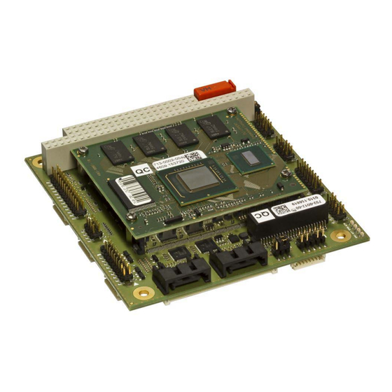
- Page 1 Cool LiteRunner-ECO ® PC/104 Carrier for CoreExpress Technical Manual TME-CLR-ECO-R0V6.docx Revision 0.6 / September 10 © LIPPERT Embedded Computers GmbH Hans-Thoma-Str. 11 D-68163 Mannheim http://www.lippertembedded.com/...
- Page 2 Technical Manual Cool LiteRunner-ECO LiPPERT Document: TME-CLR-ECO-R0V6.docx Revision 0.6 Copyright © 2010 LiPPERT Embedded Computers GmbH, All rights reserved Contents and specifications within this manual are subject of change without notice. Trademarks CoreExpress and the CoreExpress logo are registered trademarks of SFF-SIG.
-
Page 3: Table Of Contents
Table of Contents Overview Introduction ....................1 Carrier Features ..................1 Block Diagram ................... 2 Ordering Information ..................3 Cool LiteRunner-ECO Models ................ 3 Cable Sets and Accessories ................3 Specifications ..................... 4 Electrical Specifications ................4 Environmental Specifications ................. 4 Mean Time Between Failures ................. - Page 4 USB (X7, X8, X9) ..................18 Serial ATA II ports (X11, X12) ................19 High Definition Audio (X10) ................20 PS/2 Mouse and Keyboard (X19)..............20 Serial Ports (X17) ..................21 COM Connector ..................21 RS485-Termination Jumpers (X18) ..............22 Parallel Port (X20) ..................
- Page 5 Life LED ....................32 Hardware Resources ................34 Troubleshooting Appendix A, Contact Information Appendix B, Getting Help Appendix C, Further Resources Appendix D, Revision History TME-CLR-ECO-R0V6.docx Rev 0.6...
- Page 6 General Purpose Input Output Hard Disk Drive I²C Inter-Integrated Circuit Internet Protocol Liquid Crystal Display LEMT LiPPERT Enhanced Management Technology Light Emitting Diode Low Pin Count LVDS Low Voltage Differential Signaling Media Access Control Memory Management Unit Peripheral Component Interconnect...
-
Page 7: Overview
1. Overview Introduction The PC/104 Carrier Cool LiteRunner-ECO is specially designed for system on modules according to the CoreExpress specification. Depending on the used module, the board concept offers many standard I/O interfaces. Carrier Features · CoreExpress Carrier connector with 8mm stack height ·... -
Page 8: Block Diagram
Block Diagram TME-CLR-ECO-R0V6.docx Rev 0.6 Page 2 of 34... -
Page 9: Ordering Information
Ordering Information Cool LiteRunner-ECO Models Order number Description 702-0012-10 PC/104, CLR-ECO, 1.1GHz, 0°C .. +60°C, 512MB RAM 702-0012-11 PC/104, CLR-ECO, 1.1GHz, 0°C .. +60°C, 1GB RAM 702-0012-12 PC/104, CLR-ECO, 1.1GHz, 0°C .. +60°C, 2GB RAM 702-0012-13 PC/104, CLR-ECO, 1.6GHz, 0°C .. +60°C, 512MB RAM 702-0012-14 PC/104, CLR-ECO, 1.6GHz, 0°C .. -
Page 10: Specifications
Specifications Electrical Specifications Supply voltage +5 V DC, +12V DC for LVDS backlight only if needed Rise time < 10 ms Supply voltage tolerance ± 5% * Inrush current typical 2.0 A Supply current maximal 2.4 A depending on operating system and connected peripherals ** typical 1.4 A (Windows XP idle mode) * Voltage must be measured on the board, not at the power supply ** only monitor, mouse and keyboard are attached. -
Page 11: Top
TME-CLR-ECO-R0V6.docx Rev 0.6 Page 5 of 34... -
Page 12: Bottom (Vertically Mirrored)
Bottom (vertically mirrored) TME-CLR-ECO-R0V6.docx Rev 0.6 Page 6 of 34... -
Page 13: Getting Started
2. Getting Started Connector Locations PC/104 Bus (X21) Serial ATA II port ( X12) Power Connector (X26) Serial ATA II ports(X11) Gigabit LAN 1 (X14) Pin1 Pin2 TME-CLR-ECO-R0V6.docx Rev 0.6 Page 7 of 34... -
Page 14: Bottom
Bottom LVDS Connector (X4) Display Backlight Connector (X6) Pin1 Pin2 TME-CLR-ECO-R0V6.docx Rev 0.6 Page 8 of 34... -
Page 15: Jumper Locations
2.2 Jumper Locations BIOS defaults Jumper (X27) Display Voltage Selector (X5) Pin1 Pin2 TME-CLR-ECO-R0V6.docx Rev 0.6 Page 9 of 34... -
Page 16: Led Indicators
2.3 LED Indicators To facilitate problem solving, the Cool LiteRunner-ECO provides LED indicators for the following conditions: Standby Power - lights up when power for the standby domain is applied Main Power - lights up when power for the working domain is applied Suspend - blinks when board is in suspend mode Watchdog... -
Page 17: Hardware Setup
Use the cable set provided by LiPPERT to connect the Cool LiteRunner-ECO to a VGA monitor. Connect USB keyboard and mouse, respectively. Connect a hard drive with a SATA cable (not part of the cable set) to start an operation system. -
Page 18: Module Description
3. Module Description 3.1 CoreExpress Carrier connector (X2) The Cool LiteRunner-ECO provides a Carrier connector with 8 mm stack height according to the CoreExpress specification. The connector uses the following pinot. Signal Signal GND* GND* PCIE_TXAn PCIE_RXAn PCIE_TXAp PCIE_RXAp PCIE_CLKAn PCIE_CLKBn PCIE_CLKAp PCIE_CLKBp... - Page 19 Signal Signal USB_P5n USB_P4n GND* GND* USB_P3p USB_P2p USB_P3n USB_P2n USB_P1p USB_P0p USB_P1n USB_P0n USB_P6p USB_P6n USB_OC4/5# USB_OC2/3# USB _OC0/1# GND* GND* SMB_CLK SMB_DATA SMB_ALERT# SATA_LED#** GND* GND* SATA_TXAp** SATA_TXBp** SATA_TXAn** SATA_TXBn** SATA_RXAp** SATA_RXBp** SATA_RXAn** SATA_RXBn** GND* GND* CAN_TX** CAN_RX** LPC_AD3 LPC_CLK_OUT2 LPC_AD1...
-
Page 20: Display Interfaces
Signal Signal SD0_CMD WD_OUT HDA_SPKR GND* GND* HDA_BITCLK HDA_SDATAOUT HDA_SDATAIN0 HDA_RST# HDA_SYNC BIOS_DEFAULTS# PWR_GOOD PS_ON PWR_BTN# SUS_3# A100 GND* B100 GND* A101 RST_OUT# B101 SUS_4/5# A102 RST_IN# B102 BIOS_DISABLE# A103 WAKE# B103 BAT_IN A104 B104 +5V-ALWAYS A105 B105 A106 B106 A107 B107 A108... -
Page 21: Lvds Connector (X4)
LVDS There is a LVDS transmitter channel in the LVDS interface. It consists of four data pairs and one clock pair. The LVDS data pair is used to transfer pixel data as well as the LCD timing control signals. There is a connector supplying the LC-Display's inverter, too. LVDS Connector (X4) Connector type: Hirose DF14 30 pin header 1.25 mm, single row... -
Page 22: Display Backlight Connector (X6)
Display Backlight Connector (X6) Connector type: Hirose DF13 8 pin header 1.25 mm, single row Matching connector: Hirose DF13-8S-1.25C, part number 536-0007-0 00 Direction Signal Output +12V, max. 1A Output +12V, max. 1A Output +5V, max. 1A Output +5V, max. 1A Output Signal: Backlight control (level: 0..+3.3V) Output... -
Page 23: Gigabit Lan (X13, X14)
3.3 Gigabit LAN (X13, X14) There are two Intel 82574L Gigabit Ethernet controllers on board, providing two independent ports available on standard 2mm IDC10 pin headers. The 82574L is a single, compact, low power component that offers a fully integrated Gigabit Ethernet Media Access Control (MAC) and Physical Layer (PHY) port. -
Page 24: Usb (X7, X8, X9)
3.4 USB (X7, X8, X9) The Cool LiteRunner-ECO provides six USB2.0 compliant ports available on three connectors via adapter cable. The maximum bandwidth of 480MBit/s may be shared by all six ports. Please refer to the modules manual for more information on the USB controllers. Connector type: Hirose DF13 8 pin header 1.25 mm, single row Matching connector:... -
Page 25: Serial Ata Ii Ports (X11, X12)
3.5 Serial ATA II ports (X11, X12) The Cool LiteRunner-ECO provides two SATA II ports using the JMicron JMB362 Serial ATA controller. JMB362 is a single chip, 1-lane PCI Express to 2-port Serial ATA II Host Controller. JMB362 supports both AHCI and Legacy IDE controller to increase system feasibility, including Native Command Queuing, ATAPI Device, and Port Multiplier with Command-based Switching, Hot Plugging like USB and eSATA (External SATA) connection on SATA port to enhance SATA II capability. -
Page 26: High Definition Audio (X10)
3.6 High Definition Audio (X10) The Cool LiteRunner-ECO provides HD-Audio using a Realtek ALC888 High Definition Audio Codec. The following inputs and outputs are supported. · Analog Input (All ADC support 44,1k/48k/96kHz sampling rate) Microphone left and right Line In left and right ·... -
Page 27: Serial Ports (X17)
3.8 Serial Ports (X17) The Cool LiteRunner-ECO provides two multiprotocol serial ports. The maximum supported baud rates are: RS485 mode: up to 1.5 MBit/s RS232 mode: up to 500 Kbit/s Two serial ports are located on one IDC header "COM". The ports either work in RS232 or RS485 mode, selectable in BIOS on entering Special CLR Features->Toggle COM1 Mode or Toggle COM2 Mode Termination resistors for RS485 Mode can be set with jumpers on pin headers as described in that chapter. -
Page 28: Rs485-Termination Jumpers (X18)
RS485-Termination Jumpers (X18) Connector type: IDC4 pin header 2.0 mm Matching connector: 2.0 mm jumper Use 2 mm jumpers to terminate lines correctly. There are two jumpers COM1 and COM2, respectively. The RS485 termination jumpers are located at the top of the printed circuit board, see chapter 1.4 At default setting, all jumpers are off. -
Page 29: Lpt Connector
LPT Connector Connector type: IDC26 pin header 2.0 mm Matching connector: IDC26 pin female connector 2.0 mm Signal Signal Strobe Auto LF Data0 Error Data1 Init Data2 Select In Data3 Data4 Data5 Data6 Data7 Busy Paper End Select Note: Maximum current on +5V pin is 0.5A. TME-CLR-ECO-R0V6.docx Rev 0.6 Page 23 of 34... -
Page 30: Pc/104 Bus (X21)
3.10 PC/104 Bus (X21) The PC/104 bus is a modification of the industry standard (ISA) PC bus specified in IEEE P996. The PC/104 bus has different mechanics than IEEE P966 to allow the stacking of modules. The main features are: ·... -
Page 31: Micro Sd Connector (X22)
3.11 Micro SD connector (X22) Depending on the used CoreExpress module, a wide variation of micro SD cards can be used with the Cool LiteRunner-ECO. For further information on suitable micro SD cards, please refer to the corresponding modules manual. Connector type: Molex 502570-0893 Matching part:... -
Page 32: Can-Bus
CAN-Bus Depending on the used module, the CAN-Bus data lines are provided on the supervisory connector. Note: Physical implementation of the CAN-Bus must be realized outside of the Carrier. SM-Bus Interface to the modules SM-Bus. Main- and Standby Power LED Signal goes to ‘1’... -
Page 33: Bios Defaults Jumper (X27)
Connector type: Hirose DF13-10 pin header 1.25 mm Matching connector: Hirose DF13-10S-1.25C, part number 536-0009-6 00 Signal +3.3V * LAD0 LAD1 LAD2 LAD3 BIOS_DISABLE# ** LFRAME# PCI_RST# CLK_33_FWH Note: * 0.3A is the maximum current for that pin ** Signal should be pushed to ground to use an external BIOS 3.14 BIOS defaults Jumper (X27) In rare cases, it may happen that the system does not start because of certain BIOS settings. -
Page 34: Power Connector (X26)
3.16 Power Connector (X26) The onboard power supply generates all necessary voltages from the single supply of 5 Volt. The generated 3.3 Volt are available on the connectors "Backlight" and "LVDS". Note This +3.3V must not be used to supply external electronic devices with high power consumption like other PC/104 boards or displays. -
Page 35: Pci-Express Mini Card (X15)
3.17 PCI-Express Mini Card (X15) This connector provides a PCI-Express x1 lane, as well as an USB2.0 port. Connector type: Molex 67910-0001 Matching part: Mini PCI-Express card / MiniCard Signal Signal WAKE# +3.3V-ALWAYS +1.5V CLKREQ# UIM_PWR UIM_DATA REFCLK- UIM_CLK REFCLK+ UIM_RESET UIM_VPP W_DISABLE#... -
Page 36: Using The Module
4.2 Drivers Software drivers for SATA, Ethernet and audio are available for the Cool LiteRunner-ECO. These drivers can be downloaded from LiPPERT's website http://www.lippertembedded.com. Follow the installation instructions that come with the drivers. Drivers are available for Windows XP (embedded), Windows Vista, Windows 7 and Linux. Please ask sales@lippertembedded.com... -
Page 37: Gpios
GPIOs The Cool LiteRunner-ECO's general-purpose I/O signals are handled by the Nuvotond W83627HF SuperIO and LPC interface (GPIO10-GPIO17 on SuperIO == GPIO10-GPIO17 on supervisory connector). They are located in Logical Device 7 of the SuperIO and can be programmed using simple IN/OUT instructions on Index/Data registers 4Eh/4Fh. - Page 38 Life LED The Cool LiteRunner-ECO's Life LED is handled by the Nuvotond W83627HF SuperIO (GP31 on SuperIO == PIN19 on supervisory connector). This is located in Logical Device 7 of the SuperIO and can be programmed using simple IN/OUT instructions on Index/Data registers 4Eh/4Fh. /***************************************************** * Set LIFE-LED of Winbond W83627HF Super IO ******************************************************...
- Page 39 /* enter logical device 9 holding the register for GP31 */ outb(0x07, SIO_ADDR); outb(0x09, SIO_DATA); /* activate logical device 9 = Bit0 of CR30 */ outb(0x30, SIO_ADDR); outb(0x01, SIO_DATA); /* set GP31 to act as an output = Bit1 of CRF0 */ outb(0xF0, SIO_ADDR);...
- Page 40 4.4 Hardware Resources The hardware resources that will be used by the Cool LiteRunner-ECO’s devices are dependent on the used CoreExpress module. Please refer to the module’s manual for information on hardware resources or try to get them using Freeware like SiSoft Sandra Lite. The software can be downloaded from http://www.sisoftware.net/. TME-CLR-ECO-R0V6.docx Rev 0.6 Page 34 of 34...
- Page 41 · If system comes up then load at first the OPTIMIZED DEFAULTS in the BIOS setup and reboot. If you need to send the board to LiPPERT for repair, be sure you get a Return Material Authorization number (RMA) first.
- Page 42 Appendix A, Contact Information Headquarters LiPPERT Embedded Computers GmbH Hans-Thoma-Straße 11 68163 Mannheim Germany Phone +49 621 432140 +49 621 4321430 E-mail sales@lippertembedded.com support@lippertembedded.com Website www.lippertembedded.com US Office LiPPERT Embedded Computers, Inc. 5555 Glenridge Connector, Suite 200 Atlanta, GA 30342...
- Page 43 LiPPERT's website www.lippertembedded.com. Simply locate the product in question and follow the link to its manual. Returning Products for Repair To return a product to LiPPERT for repair, you need to get a Return Material Authorization (RMA) number first. Please fill in the RMA Request Form at http://www.lippertembedded.com/service/repairs.html and send it to us.
- Page 44 Appendix C, Further Resources http://www.lippertembedded.com LiPPERT Embedded Computers' website with news and detailed information. http://www.intel.com Information on the Ethernet controller. http://www.smbus.org Information about the System Management Bus (SMBus) http://www.phoenix.com/en/customer+services/bios/awardbios Additional BIOS information. http://www.realtek.com.tw Information on the HD-Audio Codec. http://www.jmicron.com Information on the SATA controller.
- Page 45 Appendix D, Revision History Filename Date Edited by Change TME-CLR-ECO-R0V0 2010-02-02 Oliver Freudenberg Draft TME-CLR-ECO-R0V1 2010-03-16 Matthias Fellhauer Clarification of some TBD values New picture on front page TME-CLR-ECO-R0V2 2010-05-20 MTBF added Some spelling corrections Released TME-CLR-ECO-R0V3 2010-06-18 Ch. 2.1 Format corrections Ch.
Need help?
Do you have a question about the PC/104 Carrier Cool LiteRunner-ECO and is the answer not in the manual?
Questions and answers