Advertisement
Quick Links
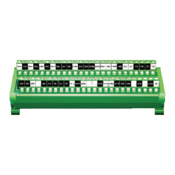
Feedthrough Connector Module
Installation Instructions
CAUTION: All unmarked terminals should be left unconnected (no connec-
tion). The unmarked terminals are used internally by the servo drive and
connecting externally could cause damage to the servo drive.
Go to http://www.automationdirect.com/sureservomanual.html to download
the complete Servo drive information.
Typical
Internal Circuit
Cable
Terminal
Pin
Block
Note: ZL-RTB50 pinouts are straight
through from pin to terminal. For example,
Connector Pin 1 = Terminal 1, Connector
Pin 2 = Terminal 2, etc.
TB1
To SureServo drive CN1 Connector.
Use ZL-SVC-CBL-50 (-1, -2) cable.
1
26
NOTE: TB2 is internally connected to the shield drain wire and should be field connected to
earth ground.
1.92" [48.6mm]
SG SG
P1
TB2
ZL-RTB50
P9333
5.46" [138.6mm]
Cable Connector
R
O
W
Pin Number Terminal ID
1
2
3
4
5
6
7
T
8
O
9
10
P
11
12
R
13
14
O
15
W
16
17
18
19
20
21
22
23
24
25
26
27
35mm
DIN
28
RAIL
29
30
B
31
O
32
33
T
34
T
35
O
36
37
M
1.89"
38
[48.1mm]
39
R
40
41
O
42
W
43
44
45
46
47
48
TB2
49
50
25
50
ZL-RTB50
ZL-RTB50 TB1 Pinouts
Description
D04+
Digital Output
D03-
Digital Output
D03+
Digital Output
D02-
Digital Output
D02+
Digital Output
D01-
Digital Output
D01+
Digital Output
DI4-
Digital Input
DI1-
Digital Input
DI2-
Digital Input
COM+
Power Common DI & DO
GND
Power VCC Ground AI
GND
Power VCC Ground AI
VGND
No Connection
MON2
Analog Monitor Output 2
MON1
Analog Monitor Output 1
VDD
Power 24V Source
T_REF
Analog Torque Input
GND
Power VCC Ground AI
VCC
Power 12V Source
OA
Position Pulse A Output
/OA
Position Pulse /A Output
/OB
Position Pulse /B Output
/OZ
Position Pulse /Z Output
OB
Position Pulse B Output
DO4-
Digital Output
DO5-
Digital Output
DO5+
Digital Output
NC
No Connection
DI8-
Digital Input
DI7-
Digital Input
DI6-
Digital Input
DI5-
Digital Input
DI3-
Digital Input
PULL HI
Position Pulse Input
/SIGN
Position Pulse Input
SIGN
Position Pulse Input
NC
No Connection
NC
No Connection
TGND
No Connection
PULSE
Position Pulse Input
V_REF
Analog Velocity Input
/PULSE
Position Pulse Input
GND
Power VCC Ground AI
COM-
Power VDD Ground DI & DO
NC
No Connection
COM-
Power VDD Ground DI & DO
NC
No Connection
COM-
Power VDD Ground DI & DO
OZ
Position Pulse Z Output
Advertisement

Related Manuals for zipLink ZL-RTB50

Summary of Contents for zipLink ZL-RTB50
- Page 1 DO5- Digital Output Cable Terminal Block DO5+ Digital Output RAIL Note: ZL-RTB50 pinouts are straight No Connection through from pin to terminal. For example, DI8- Digital Input Connector Pin 1 = Terminal 1, Connector DI7- Digital Input Pin 2 = Terminal 2, etc.
- Page 2 Feedthrough Connector Module Installation Instructions Description DIN Rail Installation The ZL-RTB50 is a DIN rail mounted feed through module designed to interface the SureServo and Removal servo drive analog and discrete control signals to a PLC or other controllers by connecting the...
Need help?
Do you have a question about the ZL-RTB50 and is the answer not in the manual?
Questions and answers