Table of Contents
Advertisement
For trailers with 2-6 electric brakes and vehicles with 12 volt negative ground systems only.
• Before beginning installation, read and become familiar with these instructions.
• Leave in tow vehicle for future reference.
• Improper installation and operation could cause personal injury and/or equipment and
property damage.
SAFETY INFORMATION
!
WARNING:
if not avoided, could result in death or serious, personal injury.
!
CAUTION:
if not avoided, could result in damage to product or property.
TIP:
Electronic Brake Controller
Hayes Brake Controller Company P/N 81760
INSTALLATION MANUAL
READ AND SAVE THESE INSTRUCTIONS
Indicates a potentially hazardous situation that,
Indicates a potentially hazardous situation that,
Contains helpful information to facilitate installation.
Advertisement
Table of Contents

Related Manuals for Hayes 81760

Summary of Contents for Hayes 81760
- Page 1 Electronic Brake Controller Hayes Brake Controller Company P/N 81760 INSTALLATION MANUAL For trailers with 2-6 electric brakes and vehicles with 12 volt negative ground systems only. READ AND SAVE THESE INSTRUCTIONS • Before beginning installation, read and become familiar with these instructions.
-
Page 2: Mounting Bracket
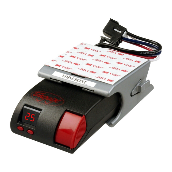
Installation DIGITAL DISPLAY SETUP ADJUSTMENT BUTTONS MANUAL OVERRIDE SLIDE LEVER Figure 1 – Front View of Engage Mounting angle and mounting direction The Engage can be mounted at any angle and in any direction. It must be mounted in a location that the driver can see and read the display. - Page 3 Controller Mounting and Installation Mounting Tinnerman Nut Bracket Self Tapping Screws Pan Head Machine Screw Figure 3 – Attachment of Mounting Bracket Controller and Bracket Mounting 1. Install the mounting bracket to a solid surface under the tow vehicle dash or other suitable location in the tow vehicle using the two machine screws and fasteners provided.
- Page 4 Read all wiring instructions prior to making electrical connections to the tow vehicle. WARNING: To reduce the risk of injury or damage to property: • Always connect the white wire first and the black wire second. • All four controller wires must be connected properly for the controller to operate correctly.
-
Page 5: Controller Wiring
Brake Controllers fitted with a connector on the wire leads, making connection a snap. Harnesses are available through all dealer resources. Ask specifically for the Hayes Brake Controller Company (HBC) brand harnesses to match your controller. The following chart describes the function of each of the controller’s wires:... -
Page 6: Special Conditions
Special Conditions For tow vehicles equipped with factory trailer towing package: • Refer to your vehicle’s owner’s manual or other information provided by the manufacturer in determining the correct connection points for the controller. • See Appendix section for partial list of manufacturer wiring harness to controller conversions. For vehicles without trailer-towing package: refer to the wiring diagram in Figure 4. - Page 7 Appendix OEM TOW VEHICLE WIRING CONVERSION CHRYSLER (THROUGH 2002) CONTROLLER FUNCTION CHRYSLER (NEW) RED W/BLACK TRACE BLACK +12 VOLT SUPPLY WHITE WITH RED TRACE WHITE W/TAN TRACE STOPLIGHT BLUE WITH WHITE TRACE BLUE BLUE TRAILER BRAKES BLUE BLACK WHITE GROUND GREEN WITH BLACK TRACE FORD (THROUGH 2002) CONTROLLER...
-
Page 8: Safety Information
Electronic Brake Controller Hayes Brake Controller Company P/N 81760 OPERATION MANUAL For trailers with 2-6 electric brakes and vehicles with 12 volt negative ground systems only. READ AND SAVE THESE INSTRUCTIONS • Before beginning operation, read and become familiar with these instructions. -
Page 9: Automatic Operation
Automatic Operation During braking, the Engage operates on a time-based circuitry. The longer the brake pedal is depressed, the greater amount of current delivered to the trailer brakes. The “power ramp time” and power is adjustable to achieve trailer brake responsiveness. The digital display will indicate the amount of power being sent to the trailer brakes. -
Page 10: Controller Features And Settings
Controller Features and Settings This controller features the following options, selections, and settings. Use illustration in Figure 1 to assist in adjustment of settings. Brake Controller Item # 81760 Quick Reference Option Available Selections Change procedure P : % of available power being sent •... - Page 11 Definitions of Options Display mode: The controller is factory pre-set to display mode P (% of maximum power) • During braking conditions - the number displayed indicates the % of power being applied to the trailer brakes. • It is recommended that display mode P (or PH for a hydraulic actuator) be used while operating the vehicle.
-
Page 12: Set Power Level
Power Ramp Time: The controller applies power to the trailer brakes based on a time-based circuitry. • The controller is factory pre-set to 3 seconds. - the number displayed indicates the selected power ramp time to deliver power to the trailer brakes. •... -
Page 13: Manual Operation
Manual Operation WARNING: Manual operation via the manual slide lever may not disengage the Cruise Control on some vehicles. • The “Manual Slide Lever” (Figure 1) is located on the front right side of the controller. • The further the manual slide lever is moved from the right to the left, the greater the amount of trailer braking effort. - Page 14 Road Test and Performance Adjustment To set the controller up for optimum performance with your tow vehicle / trailer combination, follow these steps: A. Position vehicle on a hard, flat, dry surface. B. Set the display mode to % (P or PH for Hydraulic brakes). See “Changing Display Mode” section. C.
- Page 15 Troubleshooting using the display The Digital Display will “flash” a symbol to indicate a problem with the trailer, the tow vehicle, or the brake controller. Short Circuit: The display will flash “SC”. This indicates that the controller has sensed a direct short between the controller’s output and ground.
-
Page 16: Troubleshooting
Blue controller wire not Inspect wiring and repair. trailer connection and will not connected to correct wire. flash “OC”. Learn more about trailer hitches and towing we have. Feel the difference with Hayes.
Need help?
Do you have a question about the 81760 and is the answer not in the manual?
Questions and answers