Table of Contents
Advertisement
Advertisement
Table of Contents

Subscribe to Our Youtube Channel
Related Manuals for FRC InControl TGA300

Summary of Contents for FRC InControl TGA300
- Page 1 TGA300 Rev180405 Document Number: XE-TGA3PM-R0A PRESSURE GOVERNOR, ENGINE MONITORING, AND MASTER PRESSURE DISPLAY MODELS: TGA300, TGA400 TGA300 TGA400 FIRE RESEARCH CORPORATION www.fireresearch.com 26 Southern Blvd., Nesconset, NY 11767 TEL 631.724.8888 FAX 631.360.9727 TOLL FREE 1.800.645.0074...
-
Page 2: Table Of Contents
TGA300 Rev180405 CONTENTS Table of Contents CONTENTS ........................ 2 INTRODUCTION ...................... 4 Overview ........................ 4 Features ........................4 Specifications ......................5 GENERAL DESCRIPTION ..................6 Components ......................6 Controls and Indicators ..................8 INSTALLATION ...................... 10 Install Control Module ..................10 Install Pressure Sensors .................. - Page 3 TGA300 Rev180405 Caterpillar Harness Connections ................. 35 Ford Harness Connections ................... 36 Mack Harness Connections ................. 39 Scania Harness Connections—Type A ..............40 Scania BCI Harness Connections—Type D ............41 Mercedes Harness Connections ................42 ACTROS Wiring....................43 John Deere Harness Connections ................ 44 MAN Harness Connections .................
-
Page 4: Introduction
TGA300 Rev180405 INTRODUCTION Overview The Fire Research all-in-one pressure governor and instrument panel uses state-of- the-art programmable, microprocessor technology. It maintains a steady pump discharge pressure by controlling engine speed or holds a selected engine RPM. It offers complete engine control and remote display in a single compact unit. The governor operates in one of two modes, pressure or RPM. -
Page 5: Specifications
TGA300 Rev180405 Specifications The governor is available in various models. Each model is programmed to interface with specific engines. All models provide the same functions, controls, and digital readouts for the management of pump discharge pressure. Control Module Supply Power: 12/24 VDC Supply Current: 1.8 Amp... -
Page 6: General Description
TGA300 Rev180405 GENERAL DESCRIPTION The all-in-one pressure governor and instrument panel is programmed from the factory or during installation. It is compatible with the following engines types: TGA301/401 Cummins IS Series TGA302/402 Detroit Diesel TGA304/404 Navistar TGA305/405 Caterpillar TGA306/406 Ford TGA307/406 Mack TGA308/408... - Page 7 All controls, indicators, and displays are located on the front of the control module. The TGA300 Series uses push buttons to adjust pressure and RPM settings. The TGA400 Series uses the FRC hand throttle style control knob to adjust pressure and RPM settings. (Refer to Controls and Indicators.) Intake Pressure Sensor The pressure sensor is mounted on the pump intake manifold.
-
Page 8: Controls And Indicators
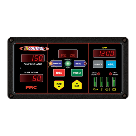
TGA300 Rev180405 Controls and Indicators All controls and indicators are located on the front of the control module. (Refer to Figure 1.) Displays and LED brightness automatically adjusts for day or night operation. PUMP DISCHARGE and PUMP INTAKE Displays Shows the pump discharge and intake pressures during normal operations. Message Display The message display shows the pressure or RPM setting during normal operations and warning alarms as they occur. -
Page 9: Figure 1. Controls And Indicators
TGA300 Rev180405 SILENCE Button Suppresses audio alarms. Used when accessing program features. MENU Button Used to access detailed information and program features. The detailed information includes the exact measure and units for monitored functions. Each time the MENU button is pressed the display scrolls to show the next value CHECK ENGINE / STOP ENGINE LEDs Repeats the engine warnings from the cab. -
Page 10: Installation
TGA300 Rev180405 INSTALLATION When the governor is programmed at the factory there is a label on the governor that specifies the engine type. If there is no label the engine type must be verified and/ or programmed. Install Control Module 1. -
Page 11: Install Pressure Sensors
TGA300 Rev180405 Install Pressure Sensors Two pressure sensors are mounted on the pump manifolds, one on the discharge and one on the intake. If there is a check valve in the discharge side of the pump, mount the discharge sensor before the check valve. T-fittings can be used to mount the pressure sensors. -
Page 12: Install Sensors
Install Remote Governor Option Refer to Install Control Module for dimensions. The remote governor is connected to power, the J1939 CAN Bus, and the FRC datalink. Refer to Wiring Section. Note: Program code P303 SYS TYPE must be set to REMOTE in the... -
Page 13: Operation
TGA300 Rev180405 OPERATION Note: When power is applied to the governor the message display shows the Software Program Revision Number for five (5) seconds. It can also be viewed with P101 code, refer to Programming Section. On power up the governor is in the pressure mode of operation. The RPM display shows engine RPM, the four LED bar graphs are green indicating readings within normal ranges, and the message display will alternate between showing the date and time. -
Page 14: Error Codes And Fault Warnings
>Broken wire / bad connector contact on sensor cable >Defective temperature sensor NO FRC >FRC datalink cable not connected / connected to wrong port >Broken wire / bad connector contact on cable DATALINK Note: E5 and E6 show on a remote governor not programmed correctly (code P303). -
Page 15: Pressure Mode Operation
TGA300 Rev180405 Pressure Mode Operation In the pressure mode of operation the PRESSURE LED is on. The governor maintains a constant discharge pressure within system capabilities. It adjusts the engine RPM automatically to compensate for variations in pressure. There is a maximum engine RPM programmed in the governor for pressure mode. If the engine reaches the programmed maximum RPM the message display flashes MAX RPM / OPERATOR and the engine RPM is not allowed to go higher. - Page 16 TGA300 Rev180405 Running Away From Water, Low Water, or No Supply Water There are situations during pump operations when there may be low or no supply water. This can be due to an empty water tank, a problem on the intake line, air in the pump, changing the water source, or an insufficient water supply.
-
Page 17: Rpm Mode Operation
TGA300 Rev180405 RPM Mode Operation In the RPM mode of operation the RPM LED is on. The governor maintains a constant engine RPM. The pump discharge pressure can vary but, as a safety feature, the governor limits the increase in pressure to 30 PSI over the last established PSI value. As the discharge pressure approaches this limit the governor automatically lowers the RPM to prevent a high pressure surge. -
Page 18: Switching Between Operating Modes
The level II programming code P221 sets the maximum RPM when the pump is operating with a discharge pressure less than 100 PSI. The factory set default is for code P221 is 1500. Access to level II programming requires a password. Contact FRC if this default limit needs to be changed. -
Page 19: Detailed Information
TGA300 Rev180405 Detailed Information The four LED bar graphs provide constant display of safe operating ranges for engine oil pressure, engine coolant temperature, transmission temperature, and battery voltage. They do not show exact numbers or units of measure. Detailed information is shown in the message display when the MENU button is pressed. -
Page 20: Preset Settings (Pressure Or Rpm)
TGA300 Rev180405 2. Press and hold PRESET button for 3 seconds. Result: RPM display flashes and shows the high-idle setting. 3. Press and hold the PRESET button and press INC/DEC or rotate the control knob to set desired RPM. 4. Release PRESET button to store the new high-idle setting. Preset Settings (Pressure or RPM) The preset button allows the operator to go to a pre-programmed pressure or RPM setting during operations. -
Page 21: Programming
TGA300 Rev180405 PROGRAMMING The following program functions are always available to view and change: P101 - Software Program Revision Number - Read Only P102 - Product Manufacturing Date - Read Only P103 - Set Current Date - Read/Write P104 - Set Current Time - Read/Write P105 - Retrieve Fault Codes - Read Only P106 - Engine Type Code - Read Only Access Program Features... - Page 22 TGA300 Rev180405 5. Press the PRESSURE button. Result: P 1 0 4 flashes in the RPM display. The message display shows SET TIME 10:30AM . 6. To Change the Time: (If not, go to step 7.) a. Press the MENU button. Result: P 1 0 4 stops flashing.
-
Page 23: Access Password Protected Programs
TGA300 Rev180405 Access Password Protected Programs The following program functions are available to view and change after the password code has been entered: Calibration Password Code 1111 C1 - Discharge Pressure Sensor Zero Calibration C2 - Intake Pressure Sensor Zero Calibration C3 - Engine RPM Calibration Refer to Calibration Section. -
Page 24: Table 4. Operator Password Protected Program Functions
TGA300 Rev180405 6. Press the MENU button to enter the programming mode to view and change parameter settings. Result: The program code stops flashing. The message display shows a selectable option or a numerical value. 7. Press the MENU button to change a selectable option or the PRESSURE or RPM button to change a numerical value. -
Page 25: Calibration
TGA300 Rev180405 CALIBRATION Three programs are available after the calibration password code has been entered: C1 - Discharge Pressure Sensor Zero Calibration C2 - Intake Pressure Sensor Zero Calibration C3 - Engine RPM Calibration Refer to Table 5. Calibration Codes Quick Reference Chart. Enter Calibration Password Code 1111 Note: To exit the programming mode, press the SILENCE button when the program code flashes in the RPM display. -
Page 26: Pump Pressure Sensor (Code C1 And C2)
TGA300 Rev180405 Pump Pressure Sensor (Code C1 and C2) The program for the pump pressure sensor(s) is self-calibrating. There are no adjustments that can be made to the sensors. When the calibration program is activated the signal from the sensor(s) is assumed to be 0 PSI. Note: If there is pressure in the plumbing where the sensor is mounted this causes the program to be calibrated to a false 0. -
Page 27: Wiring
TGA300 Rev180405 WIRING The following figures include the schematics, wiring diagrams, block diagrams, and cables for the governor. Connectors and Cables The information available on the J1939 databus varies depending on the particular engine type. When a remote governor is installed ensure that the control module program code P303 is set to REMOTE. -
Page 28: Secondary Controller, Cables And Connections
Black ECM Ground Orange Engine Control Signal To ECM White High-Idle Active Input (+12 VDC) Vent Yellow FRC Datalink (+) Green FRC Datalink (–) Access Port* Blue Buzzer Ground (300 mA max) Brown Throttle Enable Signal Output Note: An optional 6-pin connector is installed Note: Not all wires are used for all engines. -
Page 29: Pressure Sensor
TGA300 Rev180405 Pressure Sensor Pressure Sensor Cable Pressure Sensor 3-Pin Connector Cable Pin/Wire Description A/Black Ground B/Red Supply Voltage C/White Signal Pressure Sensor Top View Ground Supply Voltage Signal Output Pressure Sensor Side View Caution: The discharge and intake pressure sensors are the same size. Ensure the correct sensor is installed on the correct manifold. -
Page 30: Common Oem Diagnostic Connector
TGA300 Rev180405 Common OEM Diagnostic Connector Typical 9-Pin Deutsch Diagnostic Connector. Commonly found under the driver side dashboard. 9-Pin Connector Description Battery Ground +12 VDC J1939 CAN (+) J1939 CAN (–) J1939 Shield J1587 DATA BUS (+) J1587 DATA BUS (–) Plug Front View Plug... -
Page 31: Cummins Harness Connections
TGA300 Rev180405 Cummins Harness Connections Interface Information For use on 2004 or newer engines. The governor is designed to control engine throttle directly over the SAE J1939 databus. If the governor is being used on a COMMERCIAL CHASSIS with a Cummins Engine, ENSURE that the Cummins Engine EMERGENCY VEHICLE CALIBRATION is programmed in the engine ECM for the governor to work. -
Page 32: Detroit Diesel Harness Connections
TGA300 Rev180405 Detroit Diesel Harness Connections Interface Information Note: Refer to Figure 4. TGA 12-Pin Connector Wiring for power and interlock wire connections. For DDEC VI 2007 and Newer Engines DDEC 2/16 Pin 5 Black Wire J1939 CAN (–) 12-Pin Connector 2/17 Pin 12 Yellow Wire... -
Page 33: Navistar Harness Connections
TGA300 Rev180405 Navistar Harness Connections Interface Information The ECM must be programmed for remote variable throttle operation. Note: Check the governor engine code to verify the program setting (for J1939 control use 4C and for voltage control use 4D). Wire accordingly or change the code. -
Page 34: Navistar / International Chassis Harness Connections
Body Builder J1939 Datalink available. Remote Engine Speed must be set to ON (Feature Code 0595AHA) Connect the Body Builder J1939 Datalink to the FRC Datalink for engine control as shown below. Note: Refer to Figure 4. TGA 12-Pin Connector Wiring for power and interlock wire connections. -
Page 35: Caterpillar Harness Connections
TGA300 Rev180405 Caterpillar Harness Connections Interface Information The parameter settings for PTO Cofiguration is programmed to Remote Throttle or Remote Throttle with J1939 Speed Command. ECM software with a Personality Module release date of May08 for C7, C9, C13, C15 engines, will have the Remote Throttle with J1939 Speed Command setting available. -
Page 36: Ford Harness Connections
TGA300 Rev180405 Ford Harness Connections J1939 Interface Information A J1939 CAN input is required to provide engine information to the governor. The Ford vehicle CAN Bus information needs to be interpreted. A J1939 Translator Module with a harness to connect it to the ODB-II connector must be installed. Note: The ODB-II connector and wiring is accessed under the dash. -
Page 37: Figure 13. Ford Tga306/406 J1939 Translator Module Wiring
#8 screws. ODB-II and VDR Harness Connector To Translator Module J1 Connector 4-Pin VDR Connector To FRC VDR Pass Through 8-Pin Connector ODB-II Disconnect VDR harness 4-Pin Connector connector and connect the T-cable provided with the governor kit. -
Page 38: Figure 14. Ford Tga306/406 Pcm Wiring
TGA300 Rev180405 2011 Model F-250/350/450/550 - 6.7L Diesel Engine Stationary Elevated Idle Control (SEIC) Note: Do not press the accelerator or service brake pedal when engaging the fire pump, this prevents the switch into SEIC. Note: Refer to Figure 4. TGA 12-Pin Connector Wiring for power and interlock wire connections. -
Page 39: Mack Harness Connections
TGA300 Rev180405 Mack Harness Connections Interface Information. For V-MACK IV 07 and newer, the governor is designed to control engine throttle directly over the SAE J1939 databus. Note: Refer to Figure 4. TGA 12-Pin Connector Wiring for power and interlock wire connections. J1939 CAN Bus Control VECU Connector C... -
Page 40: Scania Harness Connections-Type A
TGA300 Rev180405 Scania Harness Connections—Type A Interface Information For use on P, R, and T-series trucks equipped with a bodywork control unit (BWS). Connector C259 is available on all vehicles ordered with any of the bodywork options. It is located on the plate for the electrical bodywork interface for body builders. Connector C259 is white and has 21 pins. -
Page 41: Scania Bci Harness Connections-Type D
TGA300 Rev180405 Scania BCI Harness Connections—Type D Interface Information For use with BCI (Bodywork Communication Interface) module. Positions in connector C493 Connector C493 is located in the bodywork console. Note: Refer to Figure 4. TGA Connector Wiring for power and interlock wire connections. 12-Pin J1939 CAN high Pin 4 Red Wire... -
Page 42: Mercedes Harness Connections
TGA300 Rev180405 Mercedes Harness Connections Interface Information Note: Refer to Figure 4. TGA 12-Pin Connector Wiring for power and interlock wire connections. For DDEC VI 2007 and newer engines. 2/16 Pin 5 Black Wire J1939 CAN (–) 12-Pin Connector 2/17 Pin 12 Yellow Wire J1939 SHIELD (Refer to... -
Page 43: Actros Wiring
TGA300 Rev180405 ACTROS Wiring Pin 1 6-Pin Optional Connector/Cable Wire Color Description Blue RPM Signal (TTL or Alternator Pulse Input) Orange Oil Sensor Signal Engine Coolant Temp Sensor Signal Black Transmission Temp Sensor Signal White Foot Pedal Signal Input Green Check Engine LED Input Note: The optional 6-Pin Connector is for inputs that are not available on J1939 12-Pin... -
Page 44: John Deere Harness Connections
TGA300 Rev180405 John Deere Harness Connections Interface Information CAN Controller will request a torque by means of TSC1. This option is disabled by default and is selectable in the Trim Options page for this application. Source address 57 should be programmed. Note: Refer to Figure 4. -
Page 45: Man Harness Connections
TGA300 Rev180405 MAN Harness Connections Interface Information Parameters for various functions can be set on the KSM using MAN-cats II. The KSM can accept the Engine speed request from the Governor on the A-CAN. Note: Refer to Figure 4. TGA 12-Pin Connector Wiring for power and interlock wire connections. -
Page 46: Iveco Harness Connections
TGA300 Rev180405 IVECO Harness Connections Interface Information The vehicles shall be ordered with EM w/ CANopen (OPT0384) and FMS (OPT14569). The CANopen XDC needs to be downloaded. This service is available from the official IVECO TeleService tool-chain worldwide. Also an adapter cable needs to be installed to connect Controller to the CAN Bus. -
Page 47: High-Idle Wiring
The high-idle is set to 1000 RPM at the factory. (This value varies depending on the specific engine.) To adjust this setting refer to High-Idle in the Operation Section. From A High-Idle Kit is available from FRC. Transmission Includes: Neutral... -
Page 48: Flyback Diode Information
(solenoid coil, relay coil, electric motor winding, etc.). It is recommended that a flyback diode be installed on inductive devices that share a common power source/ground with a FRC governor. Typical circuit showing a flyback diode installed across an inductive load. - Page 49 TGA300 Rev180405 NOTES...
- Page 50 TGA300 Rev180405 NOTES...
- Page 51 TGA300 Rev180405 NOTES...
- Page 52 TGA300 Rev180405...
Need help?
Do you have a question about the InControl TGA300 and is the answer not in the manual?
Questions and answers