Table of Contents
Advertisement
Quick Links
Advertisement
Table of Contents

Subscribe to Our Youtube Channel
Related Manuals for FRC RTU 1

Summary of Contents for FRC RTU 1
- Page 1 FOR CUMMINS CELECT and CELECT+ ENGINES SERIES M11, N14, L10 MODEL : RTU 1 OPERATING INSTRUCTIONS IDLE INCREASE SETTING DECREASE FIRE RESEARCH CORP. 26 Southern Blvd., Nesconset, NY11767 TOLL FREE 1-800-645-0074 TEL ( 516 ) 724-8888 FAX ( 516 ) 360-9727...
- Page 2 Remote Throttle Introduction: The RTU is a state of the art electronic remote throttle designed for fire apparatus equipped with the Cummins CELECT and CELECT+ electronic engine control system. This includes the M11, N14 and L10 series engines. The RTU is connected to the CELECT or CELECT+ through the J1922 data link via a twisted pair cable.
-
Page 3: Mechanical Installation
MECHANICAL INSTALLATION Before proceeding with any installation, please check to make sure you have the fol- lowing components. STOP and call the factory if any components are missing. Com- ponents supplied are as follows : 1) Throttle controller 2) Extension cable for power 3) Extension cable for J1922 data link MECHANICAL - installing the display module The control module can be mounted anywhere on the pump panel. -
Page 4: Electrical Installation
ELECTRICAL INSTALLATION Wiring for the RTU 1 system is very simple. Refer to fig 1 below. All extension cables are supplied with unique connectors that simplify the interconnections. See fig 2 for cables. 1) Use the extension cable supplied, provide 12VDC and ground to the electronic module on the wire labeled POWER on the back of the module. -
Page 5: Extension Cables
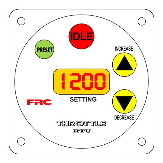
EXTENSION CABLES Figure 2 THROTTLE RTU 1 Red = 12VDC Black = GND White = From INT-110 To High Idle inside cab (see Fig 7) To J1922 data link at CELECT ECM Power 3 pins plug Deutsch DT series High Idle... - Page 6 OPERATING THE RTU Simple to use ! The RTU is engineered with ease of operations in mind. All functions on the control module are self explanatory. The LED display which shows the desired RPM setting is easily visible both day and night. How to operate : When the RTU is on, the display will show 'IDLE' to indicate that the engine is at idle.
- Page 7 FUNCTIONS FOR SWITCHES ... Figure 3 IDLE INCREASE SETTING DECREASE 1) The " IDLE " switch brings engine to idle immediately after operations 2) The " INCREASE " switch ramps engine RPM up 3) The " DECREASE " switch ramps engine RPM down 4) The "...
-
Page 8: Specifications
Specifications : Control Module : Dimensions : 4.25"W X 4.25"H X 3.75"D Response : Idle to full governed speed 3 seconds maximum Pressure Recovery : On open/close valve 1 1/2 seconds Max. RPM : 2000 RPM Operational : RPM mode : Idle to 2000 RPM Electrical : Power :... -
Page 9: Operation
X-Hi-Idle.p65 rev11Sep97nb OPTIONAL HIGH IDLE OPERATION Part # PRO-38H If you did not order the optional remote high idle, ensure that the dummy plug (supplied) is installed on the end of the high idle cable! If you did not receive a dummy plug, or have lost it, you NEED one! For wiring instructions, refer to the next page. - Page 10 Diode Note: Some FRC governors require an RPM sensor to be mounted on the drive shaft. If you have one of these units, be sure that the sensor is mounted on a section of shaft that spins even when the pump is not engaged or the high idle may not be able to function except when the pump is in gear.
- Page 11 UPS or comparable courier, as our stock permits, free of charge. After the warranty period, FRC warrants to ship to the customer by quickest way, a temporary unit (as stock permits) for the customer to use while the defective unit is being repaired in order to minimize down time.
Need help?
Do you have a question about the RTU 1 and is the answer not in the manual?
Questions and answers