
Subscribe to Our Youtube Channel
Related Manuals for Bollfilter 2200

Summary of Contents for Bollfilter 2200
- Page 1 Operating and installation instructions Electronic controller Type: 2200 Siemensstraße 10 - 14 50170 Kerpen Germany www.bollfilter.de Date Version Language Order no. Item no. 05.2015 1/32...
- Page 2 2 / 32 Operating instructions Typ 2200 Betriebsanleitung Typ 2200...
-
Page 3: Table Of Contents
Controller type 6.18 / 6.19 / 6.44 ......19 Operating instructions Typ 2200 3 / 32... - Page 4 Setting values ......... 31 4 / 32 Operating instructions Typ 2200 Betriebsanleitung Typ 2200...
-
Page 5: Basic Safety Instructions For The Electronic Controller
The local regulations for safety and the prevention of accidents must be observed. • The controller must only be operated within the permitted area of application. Operating instructions Typ 2200 5 / 32 Betriebsanleitung Typ 2200... - Page 6 6 / 32 Operating instructions Typ 2200 Betriebsanleitung Typ 2200...
-
Page 7: Technical Data Of Controller And Control Cabinet Components
Fuse protection Fuses in the control cabinet F1 to F3 each 1 A Fuses on the control circuit board Fuse F1 0.8 A T (slow-blow) Fuse F2 2.0 A T (slow-blow) Operating instructions Typ 2200 7 / 32 Betriebsanleitung Typ 2200... -
Page 8: Control Circuit Board Inputs / Outputs
The connections and designations depend on the type of filter and can be found in the respective circuit diagrams. Circuit diagrams The circuit diagrams for the controller are contained in the appendix of these operating and installation instructions. 8 / 32 Operating instructions Typ 2200 Betriebsanleitung Typ 2200... -
Page 9: Operation
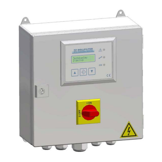
Operation Device functions and control sequence Fig. 3-1 Electronic controller type 2200 Fastening Display and operating elements Housing Master switch Connection Fig. 3-2 Display and operating elements Display screen for text display, 2 lines of 16 characters "Alarm" LED (red) "Service"... -
Page 10: Master Switch Operation Feedback Contact
When key C (number of flushes) is pressed, the number of flushing cycles which have been performed is shown on the display screen for 3 seconds. 3.1.7 Multiple flushing The number of parameterised chambers is worked off with each flushing command. 10 / 32 Operating instructions Typ 2200 Betriebsanleitung Typ 2200... -
Page 11: Dp Alarm (Flushing Frequency Monitoring)
6.64 Controller type 12 6.64 Alarm DP Controller type 13 6.64.07 Controller type 14 6.64.07 AL. DP Controller type 15 6.72 Controller type 16 6.72 Alarm DP Controller type 17 Operating instructions Typ 2200 11 / 32 Betriebsanleitung Typ 2200... -
Page 12: Text Display In "Operation" Mode
If the C key is pressed, the following message appears on the display screen: No.of flushes xxxxxx cycles Number of flushing cycles The number of flushing cycles is saved and backed up in the event of a mains failure. 12 / 32 Operating instructions Typ 2200 Betriebsanleitung Typ 2200... -
Page 13: Alarm Messages
(approximately 3 seconds). 3.4.3 Return to operation level In order to access the operation level, press keys and together until the green "Operation" LED lights up (approximately 3 seconds). Operating instructions Typ 2200 13 / 32 Betriebsanleitung Typ 2200... -
Page 14: List And Description Of Parameters
Adjustable in steps of one minute Range 0 - 59 min Factory setting Initial value 0 min Text display, line 1 P3 forced flush. Text display, line 2 XXX minutes 14 / 32 Operating instructions Typ 2200 Betriebsanleitung Typ 2200... -
Page 15: P4 Back-Flushing Time
Adjustable in steps of one second Range 5 - 100 s Factory setting Initial value 30 s Text display, line 1 P6 After blow. t. Text display, line 2 XXX seconds Operating instructions Typ 2200 15 / 32 Betriebsanleitung Typ 2200... -
Page 16: P7 Cartridge Alarm Delay Time
Adjustable in steps of 0.01 A Range 0.10 to 0.99 A Factory setting Initial value 0.4 A Text display, line 1 P9 Motor fault Text display, line 2 0000 mA 16 / 32 Operating instructions Typ 2200 Betriebsanleitung Typ 2200... -
Page 17: P10 Back Flushing Time
You can select from German, English, French and Spanish. Setting German ES Spanish French GB English Factory setting Initial setting D German Text display, line 1 P11 Language Text display, line 2 GB English Operating instructions Typ 2200 17 / 32 Betriebsanleitung Typ 2200... -
Page 18: P12 Testcode
This parameter is only visible with filter type P0 = 12, 13, 14, 15. Adjustable in steps of one second Range 0 to 99 s Factory setting Initial value 10 s Text display, line 1 P14 PET Text display, line 2 XXX seconds 18 / 32 Operating instructions Typ 2200 Betriebsanleitung Typ 2200... -
Page 19: Description And Function Of Controller
All alarms are displayed and signalled and saved via potential-free contacts. • If the controller is in parameterisation mode, flushing cannot be triggered • manually. If the "Controller type" parameter is changed, the functions are re-started. • Operating instructions Typ 2200 19 / 32 Betriebsanleitung Typ 2200... -
Page 20: Controllers Of Types 6.21/6.22/6.23 / 6.24
All alarms are displayed and signalled and saved via potential-free contacts. • If the controller is in parameterisation mode, flushing cannot be triggered • manually. If the "Controller type" parameter is changed, the functions are re-started. • 20 / 32 Operating instructions Typ 2200 Betriebsanleitung Typ 2200... -
Page 21: Controllers Of Type 6.60
1) "Control voltage monitoring" alarm Output A1, A2, A3 2) Collective fault, comprising: Output A4, A5, A6 - "Maximum differential pressure reached" alarm - "Cartridge" alarm (DP alarm flushing oil treatment) Operating instructions Typ 2200 21 / 32 Betriebsanleitung Typ 2200... - Page 22 All alarms are displayed and signalled and saved via potential-free contacts. • If the controller is in parameterisation mode, flushing cannot be triggered • manually. If the "Controller type" parameter is changed, the functions are re-started. • 22 / 32 Operating instructions Typ 2200 Betriebsanleitung Typ 2200...
-
Page 23: Controllers Of Type 6.61
Output A1, A2, A3 2) Collective fault, comprising: Output A4, A5, A6 - "Maximum differential pressure reached" alarm - "Motor fault" alarm and - "Cartridge" alarm (DP alarm flushing oil treatment) Operating instructions Typ 2200 23 / 32 Betriebsanleitung Typ 2200... - Page 24 If the controller is in parameterisation mode, flushing cannot be triggered • manually. If the "Controller type" parameter is changed, the functions are re-started. • 24 / 32 Operating instructions Typ 2200 Betriebsanleitung Typ 2200...
-
Page 25: Controllers Of Type 6.62
If the controller is in parameterisation mode, flushing cannot be triggered • manually. If the "Controller type" parameter is changed, the functions are re-started. • Operating instructions Typ 2200 25 / 32 Betriebsanleitung Typ 2200... -
Page 26: Controllers Of Type 6.64
Output A1, A2, A3 2) Collective fault, comprising: Output A4, A5, A6 - "Maximum differential pressure reached" alarm - "Motor fault" alarm and - "Cartridge" alarm (DP alarm flushing oil treatment) 26 / 32 Operating instructions Typ 2200 Betriebsanleitung Typ 2200... - Page 27 If the controller is in parameterisation mode, flushing cannot be triggered • manually. If the "Controller type" parameter is changed, the functions are re-started. • Operating instructions Typ 2200 27 / 32 Betriebsanleitung Typ 2200...
-
Page 28: Controllers Of Type 6.72
1) "Control voltage monitoring" alarm Output A1, A2, A3 2) Collective fault, comprising: Output A4, A5, A6 - "Maximum differential pressure reached" alarm - "Cartridge" alarm (DP alarm flushing oil treatment) 28 / 32 Operating instructions Typ 2200 Betriebsanleitung Typ 2200... - Page 29 All alarms are displayed and signalled and saved via potential-free contacts. • If the controller is in parameterisation mode, flushing cannot be triggered • manually. If the "Controller type" parameter is changed, the functions are re-started. • Operating instructions Typ 2200 29 / 32 Betriebsanleitung Typ 2200...
- Page 30 30 / 32 Operating instructions Typ 2200 Betriebsanleitung Typ 2200...
-
Page 31: Appendix
Appendix Setting values Operating instructions Typ 2200 31 / 32 Betriebsanleitung Typ 2200... - Page 32 32 / 32 Operating instructions Typ 2200 Betriebsanleitung Typ 2200...
Need help?
Do you have a question about the 2200 and is the answer not in the manual?
Questions and answers