Table of Contents
Advertisement
Advertisement
Chapters
Table of Contents

Related Manuals for Motorhispania MH7 Naked

Summary of Contents for Motorhispania MH7 Naked
- Page 2 NANCE OR CLARIFY SOME POINT IN THE INSTRUC- TIONS. THIS SERVICE MANUAL HAS BEEN PREPARED FOR AUTHORISED DEALERS OF G. H E MOTORHISPANIA, S.L. AND SHOULD ONLY BE USED BY QUALIFIED TECHNICAL SERVICE DEPARTMENT MECHANICS. INEXPERIENCED MECHANICS OR THOSE WITHOUT...
- Page 3 When changing parts or carrying out service work that involves dismantling, it is recommended to use genuine G.H.E. MOTORHISPANIA, S.L. spare parts, tools and service materials as specifi ed in the corresponding des- criptions All the information, fi gures and specifi cations in this manual are based on the latest approved product informa- tion available at the time of publication.
- Page 4 GENERAL CONTENTS GENERAL INFORMATION SPECIFICATIONS COMMISSIONING CHASSIS ELECTRICAL SYSTEM ENGINE ADJUSTMENT MAINTENANCE TROUBLESHOOTING...
- Page 5 GENERAL INFORMATION CONTENTS IDENTIFICATION Machine identifi cation Engine identifi cation...
-
Page 6: General Information
GENERAL INFORMATION IDENTIFICATION CHASSIS IDENTIFICATION NUMBER The chassis identifi cation number is located at the front right-hand side of the machine. The chassis number is required when requesting any motorcycle part. ENGINE IDENTIFICATION NUMBER The engine identifi cation number is located at the top right-hand side of the engine. - Page 7 SPECIFICATIONS CONTENTS GENERAL SPECIFICATIONS CHASSIS SPECIFICATIONS ENGINE SPECIFICATIONS TIGHTENING TORQUES...
-
Page 8: General Specifications
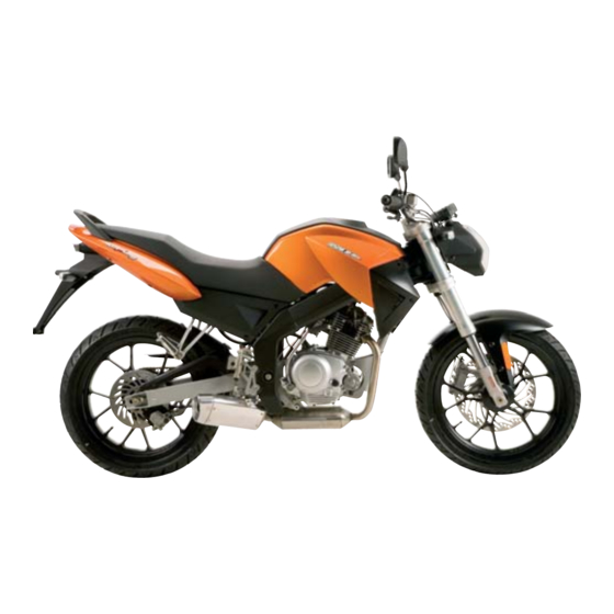
SPECIFICATIONS GENERAL SPECIFICATIONS ELEMENT SPECIFICATIONS MODEL CODE MH7 NAKED 125cc DIMENSIONS Total length: 1980 mm Total width 750 mm Height without rear-view mirrors 795 mm Distance between axles 1310 mm WEIGHT 120 kg... -
Page 9: Chassis Specifications
SPECIFICATIONS CHASSIS SPECIFICATIONS ELEMENT SPECIFICATIONS WHEELS Front wheel 2,75 x 17” Front tyre Continental 100/ 80 - 17 Front pressure 1,5 bar Rear wheel 3 x 17” Rear tyre Continental 130/70 - 17 Rear pressure 2 bar FRONT BRAKE Type Hydraulic disk, radial calliper ø... -
Page 10: Engine Specifications
SPECIFICATIONS ENGINE SPECIFICATIONS ELEMENT SPECIFICATIONS ENGINE Type of engine Single cylinder 4-stroke Make YAMAHA Cubic capacity 123,7 cc Diameter x stroke 54 mm X 54 mm Maximum power 7,5 Kw a 9000 min-1 9,4 Nm a 6500 min-1 Maximum torque ratio FUEL Recommended fuel 95 or 98 octane lead free petrol... -
Page 11: Tightening Torques
SPECIFICATIONS TIGHTENING TORQUES ITEM TIGHTENING TORQUE BODYWORK Side covers 0,1 daN·m (1 N·m) Front mudguards 0,1 daN·m (1 N·m) Rear mudguards 0,8/0,1 daN·m (8/1 N·m) Skirting 0,8/0,1 daN·m (8/1 N·m) CHASSIS Front wheel shaft 4,5 daN·m (45 N·m) Front wheel shaft clamp 1,2 daN·m (12 N·m) Rear wheel shaft nut 6,5 daN·m (65 N·m) -
Page 12: Battery Preparation (Except Maintenance-Free Batteries)
COMMISSIONING CONTENTS COMMISSIONING Battery preparation (except maintenance-free batteries) Checking levels Commissioning the fuel and oil circuits Checks before delivery to customer... -
Page 13: Commissioning
COMMISSIONING PREPARING THE BATTERY (EXCEPT MAINTENANCE-FREE BATTERIES) Regarding use of electrolyte, please read this manual carefully and fi ll the electrolyte liquid correctly, making sure not to spill any. WARNING: Check to make sure the electrolyte is the same type as in the battery. The electrolyte must always be fi... -
Page 14: Checking Levels
COMMISSIONING WARNING NEXT, THE BATTERY LEVEL MAY NEED TO BE ESTA- BLISHED AFTER A COMPLETE CHARGE, USING EX- CLUSIVELY DISTILLED WATER. CHECKING LEVELS 1) Check the gearbox oil level. 2) Check the coolant level. 3) Check the brake fl uid level. COMMISSIONING THE FUEL AND OIL CIRCUITS 1) Start up the engine and check that it is running correctly. -
Page 15: Table Of Contents
CHASSIS CONTENTS FRONT COVERS CENTRAL COVERS SEAT PILLION PASSENGER SEAT REAR COWLING GRILL NUMBER PLATE FUEL CAP TANK COVERS FUEL TANK BATTERY SUPPORT FRONT MUDGUARDS. FRONT FOOTRESTS REAR FOOTRESTS CHAIN CHAIN PROTECTOR GEAR CHANGE PEDAL FRONT WHEEL FRONT BRAKE CALLIPER FRONT BRAKE DISK REAR WHEEL REAR BRAKE CALLIPER... -
Page 16: Front Covers
CHASSIS FRONT COVERS Allen key REMOVAL • Unscrew the 3 Allen bolts (A) on each end of the cover. • Remove the front cover ASSEMBLY • To assemble, carry out the operations in reverse or- der. CAUTION WHEN YOU REMOVE THE COVERS, LEAVE THEM FACING UPWARDS TO AVOID DAMAGING THE PAINTWORK CENTRAL COVERS Allen key... -
Page 17: Seat
CHASSIS SEAT REMOVAL • Insert the key in the lock and turn 90º to the left. • Pull the seat upwards and backwards. ASSEMBLY • Fit the central tab (A) under the fl ange (B). • At the same time, fi t the two anchorages (C), located on both sides of the seat, onto the chassis securing fl... -
Page 18: Pillion Passenger Seat
CHASSIS PILLION PASSENGER SEAT Allen key REMOVAL • Remove the seat (see section). • Unscrew the 4 Allen bolts (A). • Remove the pillion passenger seat. ASSEMBLY • Fit the pillion passenger seat in its position. • Screw on the 4 Allen bolts and 4 washers. •... -
Page 19: Grill
CHASSIS GRILL REMOVAL • Remove the front covers (see section). • Remove the grill, by pulling upwards. ASSEMBLY • To assemble, carry out the operations in reverse order. NUMBER PLATE Allen key REMOVAL • Remove the seat (see section). • Remove the pillion passenger seat (see section). •... -
Page 20: Fuel Cap
CHASSIS FUEL CAP Allen key Llave Torck REMOVAL • Remove the cap (A). • Unscrew the 5 Allen bolts (B). • Remove the support orifi ce(C). • Unscrew the 3 screws (D) from the cover. • Remove the top tank cover (E). •... -
Page 21: Tank Covers
CHASSIS TANK COVERS Allen key REMOVAL • Remove the seat (see section). • Remove the front covers (see section). • Remove the cap (A). • Unscrew the 5 Allen bolts (B). • Remove the support orifi ce(C). • Unscrew the 3 bolts (D) from the central cover. •... -
Page 22: Fuel Tank
CHASSIS FUEL TANK Phillips screwdriver REMOVAL • Remove the seat (see section). • Remove the front covers (see section). • Remove the fuel cap (see section). • Remove the tank covers (see section). • Disconnect the tap from the general wiring (A). •... -
Page 23: Battery Support
CHASSIS BATTERY SUPPORT Allen key REMOVAL • Remove the seat (see section). • Remove the pillion passenger seat (see section). • Remove the right and left-hand rear cowlings (see section). • Remove the number plate (see section). • Remove the battery (see section). •... -
Page 24: Front Footrests
CHASSIS FRONT FOOTRESTS Allen key REMOVAL • Unscrew the nut (A). • Remove the bolt Allen (B). • Remove the footrests. ASSEMBLY • To assemble, carry out the operations in reverse order. REAR FOOTRESTS Callipers REMOVAL • Remove the clip and the washer (A). •... -
Page 25: Chain
CHASSIS CHAIN Set spanner Allen key REMOVAL • Situate the securing clip de (A) where it can be seen. • Remove the securing clip. • Remove the chain, by pulling it out. N.B. THE MACHINE MUST BE ON A SUPPORT WITH THE GEAR IN NEUTRAL. -
Page 26: Chain Protector
CHASSIS CHAIN PROTECTOR Allen key REMOVAL • Unscrew the 4 bolts (A). • Remove the protector. ASSEMBLY • To assemble, carry out the operations in reverse order. GEAR CHANGE PEDAL Allen key REMOVAL • Unscrew the 2 bolts (A). • Remove the gear change pedal. ASSEMBLY •... -
Page 27: Front Wheel
CHASSIS FRONT WHEEL Set spanner Allen key REMOVAL • Remove the front mudguards (see section). • Remove the (A) left-hand side wheel shaft nut (B) • Remove the mileometer take-off (C). • Loosen the bolt (D) on the right-hand fork arm securing the shaft (B). -
Page 28: Front Brake Calliper
CHASSIS FRONT BRAKE CALLIPER Set spanner Allen key REMOVAL • Unscrew the banjo bolt (A) from the bottom end of the brake hose. • Drain the brake fl uid. • Unscrew the 2 bolts (A) and washers. • Remove the calliper. N.B. -
Page 29: Rear Wheel
CHASSIS REAR WHEEL Set spanner Allen key REMOVAL • Loosen the tensioner locking nut (A). • Tighten the bolt (B) right down. • Remove the 2 nuts (C) from the shaft. • Remove the 2 tensioners (D). • Push the wheel forwards. •... - Page 30 CHASSIS REAR WHEEL Set spanner Allen key ASSEMBLY N.B. FIT THE TENSIONERS IN THEIR CORRECT POSITION. • Fit the tensioner (A) on the swinging arm. • Insert the shaft in the tensioner. • Fit the brake calliper - support. • Fit the separator. •...
-
Page 31: Rear Brake Calliper
CHASSIS REAR BRAKE CALLIPER Set spanner Allen key REMOVAL • Unscrew the banjo bolt (A) from the bottom end of the brake hose. • Drain the brake fl uid. • Remove the rear wheel (see section). • Unscrew the 2 bolts (B) securing the support. •... -
Page 32: Rear Brake Fluid Reservoir
CHASSIS REAR BRAKE FLUID RESERVOIR Phillips screwdriver Allen key REMOVAL • Open the reservoir cover (A). • Drain the fl uid. • Unscrew the banjo bolt (C). • Unscrew the 2 bolts (B). • Remove the reservoir. N.B. PLACE A CONTAINER UNDERNEATH TO DRAIN THE FLUID. -
Page 33: Rear Sprocket
CHASSIS REAR SPROCKET Set spanner REMOVAL • Remove the rear wheel (see section). • Unscrew the 5 bolts (A). • Remove the rear sprocket. ASSEMBLY • To assemble, carry out the operations in reverse order. PROP-STAND Set spanner REMOVAL • Remove the spring (A). •... -
Page 34: Front Brake Lever
CHASSIS FRONT BRAKE LEVER Allen key REMOVAL • Unscrew the bolt (A) and the securing nut. • Remove the lever. ASSEMBLY • To assemble, carry out the operations in reverse order. FRONT BRAKE FLUID RESERVOIR Allen key • Remove the rear-view mirror (A). •... -
Page 35: Throttle Control
CHASSIS THROTTLE CONTROL Allen key REMOVAL • Remove the protective rubber (A). • Loosen the throttle cable tensioner (B). • Remove the cover (C). • Disconnect the cable (D). • Unscrew the 2 Allen bolts (E) from the clamp. • Remove the throttle control. ASSEMBLY •... -
Page 36: Commutator
CHASSIS COMMUTATOR Allen key REMOVAL • emove the rear-view mirror (A). • Remove the choke cable (B). • Remove the clutch lever (see section). • Unscrew the 2 bolts (C). • Remove the commutator. ASSEMBLY • To assemble, carry out the operations in reverse order. HANDLEBARS Phillips screwdriver... -
Page 37: Instrument Panel
CHASSIS INSTRUMENT PANEL Phillips screwdriver REMOVAL • Disconnect from the general wiring (A). • Unscrew the 3 support bracket bolts (B). • Remove the instrument panel. ASSEMBLY • To assemble, carry out the operations in reverse order. IGNITION SWITCH Allen key REMOVAL •... -
Page 38: Exhaust Pipe
CHASSIS EXHAUST PIPE Set spanner Allen key REMOVAL • Unscrew the 2 bolts (A). • Remove the central nut (B) located at the bottom of the engine. • Remove the pipe and the gasket. WARNING CHECK THAT THE EXHAUST PIPE IS COLD. ASSEMBLY •... -
Page 39: Air Filter
CHASSIS AIR FILTER Phillips screwdriver REMOVAL • Remove the seat (see section). • Remove the 6 bolts (A) securing the fi lter cover. • Remove the cover (B) by pulling upwards. • Remove the fi lter (C) by pulling upwards. •... -
Page 40: Swinging Arm
CHASSIS SWINGING ARM Set spanner REMOVAL • Remove the chain protector (see section). • Remove the chain (see section). • Remove the rear wheel (see section). • Remove the shock absorber (the bottom part) (see section). • Remove the rear brake cable clamp located at the bottom of the swinging arm. -
Page 41: Forks
CHASSIS FORKS Allen key REMOVAL • Remove the handlebars (see section). • Remove the front wheel (see section). • Remove the headlight (see section). • Remove the instrument panel (see section). • Remove the ignition switch (see section). • Remove the front mudguards (see section). •... - Page 42 CHASSIS • Unscrew the plug (A). • Remove the O-ring (B), the spacer (C) and the spring (D). • Drain the hydraulic fl uid into a container. • Unscrew the bolt (E) and the seal (F). • Remove the dust guard (G), the locking ring (H), the airtight seal (I) and the ring (J).
-
Page 43: Carburettor
CHASSIS CARBURETTOR Set spanner REMOVAL • Remove the seat (see section). • Remove the fuel tank (see section). • Disconnect the carburettor air intake (A). • Disconnect the throttle cable (B). • Disconnect the fuel intake (C). • Disconnect the choke cable (D). •... - Page 44 ELECTRICAL SYSTEM CONTENTS FRONT HEADLIGHT – MAIN BEAM/DIPPED BEAM BULB FRONT HEADLIGHT - SIDELIGHT REAR LIGHT FRONT AND REAR TURN INDICATORS NUMBER PLATE LIGHT RELAY E.C.U. COIL REGULATOR FUSE BATTERY INSTRUMENT PANEL...
-
Page 45: Front Headlight Main Beam/Dipped Beam Bulb
ELECTRICAL SYSTEM FRONT HEADLIGHT Allen key MAIN BEAM/DIPPED BEAM BULB • Remove the two bolts (A), one on each side, securing the headlight housing (B). • Tilt the headlight housing (B) downwards to be able to access the headlight. • Loosen the two bolts (C), one on each side, securing the headlight to the chassis. -
Page 46: Front Headlight - Sidelight
ELECTRICAL SYSTEM FRONT HEADLIGHT - SIDELIGHT Allen key • Remove the front headlight main beam/dipped beam bulb (see section). • Loosen the two bolts (A) securing the headlight. • Tilt the headlight (B) forwards. • Pull down the headlight housing (C) to extract the hea- dlight. -
Page 47: Rear Light
ELECTRICAL SYSTEM REAR LIGHT Set spanner REMOVAL To replace the rear light, these operations must be ca- rried out by way of the step for the rear wheel: • Disconnect the light from the wiring (A). • Hold the light with one hand. •... -
Page 48: Front And Rear Turn Indicators
ELECTRICAL SYSTEM FRONT AND REAR TURN INDICATOR Phillips screwdriver LIGHTS REMOVAL • Loosen the bolt (A) holding the screen. • Remove the screen (B). • Turn the bulb (C) to the left and remove it. ASSEMBLY • To assemble, carry out the operations in reverse order. WARNING KEEP THE SWITCH DISCONNECTED DURING THIS OPE- RATION. -
Page 49: Number Plate Light
ELECTRICAL SYSTEM NUMBER PLATE LIGHT Allen key REMOVAL • Remove the bolt (A) holding the screen. • Then pull out the bulb (B) while holding the bulb holder (C) with the other hand. ASSEMBLY • To assemble, carry out the operations in reverse order. -
Page 50: Relay
ELECTRICAL SYSTEM RELAY REMOVAL • Remove the seat (see section). • Disconnect the relay (A). ASSEMBLY • To assemble, carry out the operations in reverse order. E.C.U. REMOVAL • Remove the seat (see section). • Remove the fuel tank (see section). •... -
Page 51: Coil
ELECTRICAL SYSTEM COIL REMOVAL • Remove the seat (see section). • Remove the fuel tank (see section). • Remove the 2 bolts (A). • Remove the coil (B). ASSEMBLY • To assemble, carry out the operations in reverse order. REGULATOR REMOVAL •... -
Page 52: Battery
ELECTRICAL SYSTEM BATTERY REMOVAL • Remove the seat (see section). • Disconnect the two connecting cables. Negative (A) Positive (B). ASSEMBLY • To assemble, carry out the operations in reverse order. WARNING TO FIT A NEW BATTERY, REVIEW THE SECTION “PREPARING THE BATTERY”... - Page 53 ELECTRICAL SYSTEM DASHBOARD CONFIGURATION OR ADJUSTMENT • The instrument panel has two adjustment buttons: SET(1) button and MODE(2) button. • Aim of the buttons is: Allow functions scrolling. Regulation of the clock. Set to zero the TD, AVE , LAP and MAX values. Entering the Set-up menu to modify the wheel cir- cumference value, the measurement unit value of dis- tance, the number of impulses for every turn of the...
- Page 54 ELECTRICAL SYSTEM ATTENTION BEFORE GOING ON PLEASE CAREFULLY READ ELEC- TRICAL FEATURES AT PARAGRAPH 14 VERIFYING THE FUNCTIONAL VOLTAGES FOR OPERA- TION OF THE SPEEDOMETER 1. AIM This document constitutes the technical manual with functional specifi cations for MHRN speedometer. 2.
- Page 55 ELECTRICAL SYSTEM 4. COMPONENTS DEFINITION 4.1. LCD Display 4.2. Mode and Set buttons Picture 4-1: lcd display The device has got two buttons normally OPEN that close on a NEGATIVE. Button 1: MODE Button 2: SET Functions and use of buttons is described in following pa- ragraphs of the technical manual.
- Page 56 ELECTRICAL SYSTEM 5.3. Trip function (TD) This function describes the correct working/visualiza- tion of the board automatic partial totalizer. This function is always represented on digit 13÷16 and by logo TD (pic.5-4). The visualized data represents the vehicle covered distance expressed in miles or km (depending on the selected measurement unit), with resolution 0.1 Picture 5-4: Partial covered distance (miles or km).
- Page 57 ELECTRICAL SYSTEM Clock regulation can be done by pushing Mode button until when only segments related to TIME function are active (about 5sec.), while all the others are off (see picture 5-6). It’s possible to modify in series: fi rst the hours then the minutes, this depends by the selected data (that will be shown blinking with f=1Hz, Duty=50%).
- Page 58 ELECTRICAL SYSTEM 5.5. Automatic Chronometer Function (LAP) This function describes the correct working/visualization of the chronometer related to TD and AVE. This information is visualized by using digit 13÷16 and logo LAP . The data represents the effective route time of the vehi- cle in the form mm:ss if hours = 0 (pic.5-8) and in the form hh:mm if hours >...
- Page 59 ELECTRICAL SYSTEM The data isn’t memorized in a permanent mode. It’s possible to set to zero the counter of this parameter pushing the Set button for about 2 se- conds, in correspondence of the function AVE, till when the value 0.0 appears. The setting to zero of AVE, which is possible both when the vehicle is stopped or when the vehicle is run- Picture 5-10: Average speed indi-...
- Page 60 ELECTRICAL SYSTEM 5.8. Battery charge level function The information is visualized on the bottom left part by using the graphic bar, accompanied by the battery symbol ignition, as shown in picture 5-12. The graphic bar, updated every 0,5 seconds, is mana- ged by the following table: Picture 5-12: battery level Voltage [V]...
- Page 61 ELECTRICAL SYSTEM 6.2. Fuel Level Alarm Every time that fuel level sensor closes on earth, the icon is visualized on the display (fuel reserve symbol) as shown in picture 6-2. At the same time the microcontroller will turn on the related light on the dial (see paragraph 7.4). The icon disappears and the light turned on when the sensor opens again the contact.
- Page 62 ELECTRICAL SYSTEM 8. SET-UP MENU The entry in the set-up menu is only possible when the vehicle is stopped by pushing at the same time the Mode and the Set button for about 04 seconds regardless the visualized function. On the display the “SET Par” logo will appear fi xed (as in the picture 8-1) for the entry in the set-up menu of Picture 8-1: parameters set-up...
- Page 63 ELECTRICAL SYSTEM 8.2. Modifi cations allowed to user (input #5 discon- nected) 8.2.1. Distance unit measurement regulation The display the symbols km/h and mph will be shown and the selected value will be shown fi rst blinking (f=1Hz, Duty=50%) (picture 8-2). Pressure on Set button causes the change in shown blinking unit, while the Mode button pressure, in corres- pondence of blinking unit, allows to select the same...
- Page 64 ELECTRICAL SYSTEM Obs. 8-3: Regulation: from 1.000mm to 2.500mm with step of 1mm. Setting a value over 2.500mm, will cause the circumference set to default value (1.845mm) Obs. 8-4: Once inside the regulation menu: • If 20 sec. will pass without the button mode is pushed, or •...
- Page 65 ELECTRICAL SYSTEM The information concerning the number of impulses of the engine is saved in memory. Obs. 8-7: Once inside the regulation menu: • If 20 sec. will pass without the button mode is pushed, or • If the vehicle is turned on (speed>0), or •...
- Page 66 ELECTRICAL SYSTEM 9. MODE AND SET BUTTONS FUNCTION Aim of the buttons is: • Allow functions scrolling • Regulation of the clock • Set to zero the TD, AVE , LAP and MAX values. • Entering the Set-up menu to modify the wheel circumfe- rence value, the measurement unit value of distance, the number of impulses for every turn of the wheel and of the engine, and fi...
- Page 67 ELECTRICAL SYSTEM 10. START-UP At the start-up (key from OFF to ON), the system gives to the user some information which are shown in following screens (or pages): • First page: visualization of the release date and software’s version (for about 2 seconds). This information is shown only during the fi...
- Page 68 ELECTRICAL SYSTEM Engine turn impulses Selected wheel circumference Distance measurement unit Wheel turn impulses Graphic bar information Picture 10-3: third page Obs. 10-1: If during the Start up phase the vehicle starts (speed>0), the instrumentation will interrupt the check and will return to the standard operation mode. Obs.
- Page 69 ELECTRICAL SYSTEM 11. SLEEP-MODE AND WAKE-UP 11.1. Sleep mode The microcontroller enters the sleep-mode phase, with low current absorption, when the key is turned off. To reach this aim, during sleep mode phase, every activi- ty will be interrupted, the display and its backlighting will be off, only the update of current hour is on Sleep-mode phase can always be reached, regardless from selected function.
- Page 70 ELECTRICAL SYSTEM 13. TEST MENU ATTENTION USING OF TEST PROCEDURE NEEDS ONLY QUALI- FIED STAFF. TO AVOID EVERY KIND OF DRAWBACKS OR BAD FUNCTIONING PLEASE DO NOT USE Foreseen menu function and do not disclose the content of this chapter to fi nal end user. Entry in test menu is allowed only during installation phase of device on the vehicle, by placing at earth the test wire #5 (usually without cable) and keeping pushed...
- Page 71 ELECTRICAL SYSTEM Now the system starts the display check by lighting all segments in series; at the end of the check screen in picture 5-2 will be visualized, the total distance covered from the vehicle appears (unit of measurement km). •...
- Page 72 ELECTRICAL SYSTEM 13.3. Erasing procedure prom (E PROM) During the tests and the controls of the instrumen- tation, it’s useful erasing the E2prom memory. To enter the procedure the Md button must be pres- sed inside the correspondent screen in Test Menu (by using Up and Down buttons the selection will occur, pic.
- Page 73 ELECTRICAL SYSTEM 14. ELECTRICAL FEATURES Maximum working features: Feature Simb. MIn. Max. Units Param. No. Max working voltage Storage Temperature °C Max supplied current from pin 7 Hall Max current applicable to inputs InMax Max current applicable to outputs outMax Normal working features: Max.
- Page 74 ELECTRICAL SYSTEM 15. CONNECTOR PINOUT CONFIGURATION The connector is directly placed on the bottom side of the board. Producer MOLEX Part Number 43045-1818 Meaning Meaning -------- Not connected Sensor input Left Indicator ------- Not connected -------- Not connected High Beam lights -------- Not connected Right Indicator -------- Not connected...
- Page 75 ENGINE TABLE OF CONTENTS CHARACTERISTICS ENGINE CAPACITIES ENGINE MARKING SPECIAL IMPORTANT POINTS OIL AND FUEL TIGHTENING TORQUES SPECIAL TOOLS CYLINDER HEAD / CYLINDER / PISTON CHECKING THE CYLINDER CHECKING THE PISTON CHECKING THE PISTON RINGS INSTALLING THE PISTON RINGS ON THE PISTON SETTING THE TIMING CLUTCH CHECKING THE CLUTCH...
-
Page 76: Capacities
ENGINE CHARACTERISTICS ENGINE Type 4-stroke single-cylinder By natural air circulation Cooling 54 x 54 mm Bore x stroke 123.7 cc Cubic capacity By chain Distribution Single overhead camshaft, 2 valves Oil bath multi-disc clutch with manual control (4 smooth discs, Clutch 5 lining discs) 5 speed... -
Page 77: Special Important Points
ENGINE SPECIAL IMPORTANT POINTS OIL AND FUEL This engine is designed to run on 95 or 98 un- leaded fuel only. Fuel pipes must absolutely be changed if there are any wear marks, cracks, etc. If they have to be changed, install genuine pi- pes. -
Page 78: Tightening Torques
ENGINE TIGHTENING TORQUES Cylinder head 1 m.daN/2.2 m.daN Cylinder casings 1 m.daN Transmission cover 1 m.daN Inlet manifold 1 m.daN Camshaft gear 2 m.daN Camshaft gear cover 1 m.daN Chain tensioner 1 m.daN Chain tensioner 1 m.daN Conrod and crankshaft assembly gear 7 m.daN Clutch housing 6 m.daN... -
Page 79: Special Tools
ENGINE SPECIAL TOOLS Used Used MH Code Designation MH Code Designation with with Casing Casing extractor opening Pin nut 2541002000214 2541002000221 2541002000216 plate + opening twl Shouldered Clutch lever 2541002000215 centering 2541002000214 2541002000222 lip seal fitting tool tool Pin Ø12 Fixed flange 2541002000216 2541002000221... -
Page 80: Cylinder Head / Cylinder / Piston
ENGINE CYLINDER HEAD / CYLINDER / PISTON PUTTING THE ENGINE ON THE STAND • Fit the engine to adapter P/N 758464. • Put the assembly on stand P/N 64765 clamped in the jaws of a vice. • Remove the bolt (1) in order to drain off the gearbox Tightening torque: 2 m.daN. - Page 81 ENGINE • Using a wrench, turn the crankshaft counterclockwise so as to align the crankshaft gear mark (I) with the cylin- der head mark (A). • Immobilize the conrod and crankshaft assembly by means of the fl ywheel magneto nut. •...
- Page 82 ENGINE • Slacken off the cylinder head/cylinder 6 mounting bolts in the order shown, in 2 or 3 stages. • Remove the cylinder head. REMOVAL OF THE CYLINDER / PISTON • Removal of the metal gasket (6) and the 2 centring pillars (7).
-
Page 83: Checking The Cylinder
ENGINE CHECKING THE CYLINDER • The cylinder should show no traces of scoring or seizure. • Cylinder diameter: 54.000 to 54.018 mm. CHECKING THE PISTON • The piston should show no traces of scoring or seizure. • The rings must be free in their grooves. •... -
Page 84: Installing The Piston Rings On The Piston
ENGINE INSTALLING THE PISTON RINGS ON THE PISTON • Proceed in the following order in order to install the oil control rings. • Install the spring (1) (no special direction). • Install the 2 piston rings (2) on each side of the spring by offsetting the gap of each ring (no special direction). - Page 85 ENGINE • Position the piston ring gap as follows. 1. Top compression ring gap. 2. Compression ring gap. 3. Upper oil control ring gap. 4. Lower oil control ring gap. FITTING THE CYLINDER • Install the cylinder base gasket and the 2 guiding pillars on the crankcase.
-
Page 86: Setting The Timing
ENGINE FITTING THE CYLINDER HEAD • Fit the 2 guiding pillars (1) and the metal gasket (2) on the cylinder. • Fit the chain pad (3). • Install the cylinder head. • Slightly lubricate the thread of the 6 screws that secure the cylinder head. - Page 87 ENGINE • Fit the gear in the chain on one of the sides. • Using a tool with a small diameter, fi nish fi tting the chain around the gear. • Fit the gear on the camshaft. • Make sure the mark (I) of the camshaft gear isaligned with the mark (B) of the cylinder head.
- Page 88 ENGINE • Loosen the chain tensioner as indicated. • Fit the chain tensioner seal (respect the position of ins- tallation). • Install the chain tensioner and the 2 attachment screws. Tightening torque: 1 m.daN. • Install the tensioner cap. Tightening torque: 0.8 m.daN. •...
- Page 89 ENGINE • Install the timing gear (1) cover. Tightening torque: 1 m.daN. • Install the timing mark cap (2). • Fit the central cap (3).
-
Page 90: Clutch
ENGINE CLUTCH REMOVAL OF THE CLUTCH REMOVAL OF THE OIL PUMP • Remove the starter motor. • Remove the transmission cover 9 fi xing bolts. • Remove the transmission cover. Tightening torque: 1 m.daN. • Remove the paper gasket (1) and the 2 locating pins (2). •... - Page 91 ENGINE • Fold down the clutch nut (6) lockwasher tab (5). • Lock the clutch main shaft (7) with tool P/N 753731. • Remove the nut and the washer. • Immobilize the gears by fi tting a copper washer (A) bet- ween the gears.
- Page 92 ENGINE • Remove the pinion (13). • Remove the key (14) from the crank. • Remove the centrifugal fi lter (15). • Remove the drive gear from the oil pump (16). • Remove washer (17). • Remove the circlip. • Remove the pinion (18). •...
-
Page 93: Checking The Clutch
ENGINE CHECKING THE CLUTCH • Measure the thickness of the lined discs. • Disc thickness: 3 mm. • Utilisation limit: 2.8 mm. • Measure the length of the springs. • Spring length: 33 mm. • Utilisation limit: 31 mm. • Check the condition of the notches of the clutch housing and the condition of the splines of the clutch gear. -
Page 94: Checking And Cleaning The Oil Filters
ENGINE CHECKING AND CLEANING THE OIL FILTERS. • Clean the centrifugal fi lter by dipping it into a cleanser. • Blow through the holes (A) of the centrifugal fi lter with compressed air. • Check and clean the strainer. (1) - Page 95 ENGINE FITTING THE OIL PUMP • Install the oil pump and a new gasket (1). Tightening torque: 0.7 m.daN. • Install the tapered washer (2), the humped side to the oil pump. • Install the pinion. (3) • Install the circlips. (4) FITTING THE CLUTCH •...
- Page 96 ENGINE • Immobilize the gears by fi tting a copper washer (A) bet- ween the gears. • Tighten the nut. (15) Tightening torque: 7 m.daN. • Lock the clutch main shaft 16 with tool P/N 753731. • Tighten the nut. (17) Tightening torque: 6 m.daN.
- Page 97 ENGINE • When re-assembling, ensure that the marks (B) on the smooth discs are offset by 90° from the others. • Fit the pressure plate (20) lining up the arrow (C) on the plate with the round imprint (D) on the clutch main shaft.
-
Page 98: Adjusting The Clutch Control Lever
ENGINE ADJUSTING THE CLUTCH CONTROL LEVER • Slacken the pressure plate locknut (1). • Bring the lever into contact with the control rod. • Check that the mark (A) of the lever is lined up with the notch (B) of the crankcase. •... -
Page 99: Magneto Flywheel
ENGINE MAGNETO FLYWHEEL TO REMOVE THE MAGNETO FLYWHEEL • Remove the 7 bolts that secure the cover. • Remove the fl ywheel magneto cover. • Remove the paper gasket and the two 2 centering pins. Tightening torque: 1 m.daN. • Immobilize the rotor (1) using the fl ywheel clamp P/N 68570. -
Page 100: Checking The Overrunning Clutch
ENGINE CHECKING THE OVERRUNNING CLUTCH • Rotate the overrunning clutch by hand. • It must rotate in direction (A). • It must be block in direction (B). • If it doesn’t, replace the overrunning clutch. -
Page 101: Gearbox/Conrod And Crankshaft Assembly
ENGINE GEARBOX/CONROD AND CRANKSHAFT ASSEMBLY REMOVAL OF THE GEARBOX REMOVAL OF THE CRANKSHAFT • Remove the cylinder head. • Remove the cylinder and the piston. • Remove the primary drive. • Remove the fl ywheel magneto rotor. • Remove the gear shift shaft (1). •... - Page 102 ENGINE • Remove: • The circlip. (4) • The washer (5). • The starter drive pinion. (6) (*) • The plain washer. (7) • The circlip. (8) (*) The kick starter pinion is on the engine but it is not used. •...
- Page 103 ENGINE • Remove the 10 screws from the LH crankcase, 2 of which are located on the RH crankcase. • Remove the 2 nuts that secure the engine to the fi xture. • Remove the RH half crankcase and the 2 centering pins.
- Page 104 ENGINE • Fit to casing with tool P/N 64706 fi tted with plate P/N 758466. • Fix the assembly to the casing using 4 bolts (1). • Tighten the tool centre screw holding the crank with one hand on the other side until it is fully extracted. •...
-
Page 105: Checking The Crankshaft And Conrod Assembly
ENGINE CHECKING THE CRANKSHAFT AND CONROD ASSEMBLY • Using a set of shims, check the big end side play. • The maximum side play on the conrod end must not exceed: 0.45 mm. • The out-of-round values measured on the ends of the crank should not exceed 0.03 mm and must be measu- red: •... -
Page 106: Checking The Gearbox
ENGINE CHECKING THE GEARBOX • Check the condition of the ends (A) and the guide (B) of the shift forks. • Check the condition of the grooves (C) of the selector cylinder. • Check the condition of every gear. • Check that every gear slides and rotates on the corre- ponding shaft. - Page 107 ENGINE FITTING THE CRANK ASSEMBLY RH BEARING • The bearing is positioned into the casing by means of a press. FITTING THE SEALS AND GASKETS • Using tool P/N 753729, fi t the clutch lever seal. • The gearbox output and gear shift shaft seals are to be positioned fl...
- Page 108 ENGINE FITTING THE CONROD AND CRANKSHAFT ASSEMBLY • Fit the conrod and crankshaft assembly into the LH crankcase. • Tighten pin P/N 64712 at the end of the crank ass- embly. • Fit to casing with tool P/N 64706 fi tted with plate P/N 758466.
- Page 109 ENGINE • Install the shift fork as shown. • Marking (A) is upwards. • Install the selector cylinder (2). • Fit the shift fork guides into the grooves of the cylinder. • Install the shift fork pins (3). • Install the balance shaft (4) by lining up the mark of the balance shaft pinion with the mark of the conrod and crankshaft assembly.
- Page 110 ENGINE • Make sure the gasket seat of the RH and LH crankca- ses is perfectly clean. • Fit the 2 centring pins (5). • Put gasket seal paste on the LH crankcase gasket seat. • Place the RH casing over the LH casing assembly. No tools are necessary for assembling the casings, which shall be carried out without effort.
- Page 111 ENGINE • Install the starter pinion (7). • Install the starter pinion holder plate (8). Tightening torque: 0.8 m.daN. • Install the timing chain. • Install the the chain tensioner slipper. Tightening torque: 1 m.daN. • Fit: • The circlip (9). •...
- Page 112 ENGINE • Install the star locking lever (10) and its spring (11). Tightening torque: 1 m.daN. • Install the star (12) and its 2 centering pins. NOTE WHEN RE-INSTALLING, FIT A SCREW WITH STANDARD THREAD LOCK. Tightening torque: 0.8 m.daN. •...
-
Page 113: Miscellaneous Operations
ENGINE MISCELLANEOUS OPERATIONS REMOVAL OF THE CAMSHAFT AND/OR ROCKERS • Remove the cylinder head. • Remove the stopper plate. (2) • Remove the camshaft (1). • Using the intertia extractor. • Remove the cam follower shafts. • Remove the inlet (3) and exhaust (4) rockers. REMOVAL OF THE VALVES OR VALVE STEM SEALS •... - Page 114 ENGINE • Remove: • The upper cup (1). • The spring (2). • The valve (3). • Remove the 2nd valve in the same way. NOTE WHEN RE-INSTALLING, LUBRICATE THE 2 HALF CONES (4) SO AS TO HOLD THEM IN THE GROOVE OF THE VALVE’S STEM.
-
Page 115: Checking The Valve Clearance
ENGINE CHECKING THE VALVE CLEARANCE • Removal of the camshaft gear cover (1). • Removal of the central plug (2).. • Using a wrench, turn the crankshaft counterclockwise so as to align the crankshaft gear mark (I) with the cylin- der head mark (A). -
Page 116: Carburettor
ENGINE CARBURETTOR REMOVAL OF THE THROTTLE VALVE • Unscrew the carburettor chamber cap (1). • Dismantle the valve equipped with its needle, spring and carburettor chamber cap. • Dismantle the needle (2) by pushing it out in order to remove the clips (3). - Page 117 ENGINE • Remove the paper gasket. • Remove the fl oat (3) pin (2). • Remove the fl oat and the needle valve. • Remove the idle jet (4). • Remove the main jet (5). • Remove the jet spray nozzle (6). •...
- Page 118 ENGINE REMOVAL OF THE ENGINE SPEED ADJUSTER SCREW AND MIXTURE CONTROL SCREW • Turn clockwise the engine speed adjuster screw (1) and mixture control screw (2) while counting the number of turns until they are screwed home. • When re-fi tting, this operation allows you to put them back to their initial adjutment position.
- Page 119 ENGINE RE-FITTING THE JETS, FLOAT AND NEEDLE VALVE • Fit the jet spray nozzle (1). • Fit the main jet (2). • Fit the idle adjuster screw (3). • Position the needle valve (4) on the tongue of the fl oat (5). •...
- Page 120 ADJUSTMENT CONTENTS TRANSMISSION CHAIN TENSION LUTCH TENSION THROTTLE CONTROL TENSIONING THE FRONT BRAKE TENSIONING THE REAR BRAKE PEDAL CHANGING CARBURETTOR...
-
Page 121: Transmission Chain Tension
ADJUSTMENT TRANSMISSION CHAIN TENSION Set spanner To adjust the tension of the transmission chain, the steps described below must be carried out on both sides. • Loosen the two nuts (A) securing the rear wheel. • Loosen the securing nut (B). •... -
Page 122: Lutch Tension
ADJUSTMENT CLUTCH TENSION To increase or decrease the clutch tension: • Remove the protective rubber (A). • Loosen the locking wheel (B). • Turn the wheel (C) to tighten or loosen the cable. • Use the locking wheel (B) to set the position. THROTTLE CONTROL To increase or decrease the throttle twist-grip tension: •... -
Page 123: Tensioning The Front Brake
ADJUSTMENT TENSIONING THE FRONT BRAKE Allen key To increase or decrease the tension of the front brake: • Loosen the securing nut (A). • With a No.4 Allen key (B), increase or decrease the action of the front brake. • Use the securing nut (A) to set the position. TENSIONING THE REAR BRAKE To increase or decrease the tension of the rear brake: •... -
Page 124: Carburettor
ADJUSTMENT GEAR CHANGE PEDAL Adjust the position of the gear change pedal to adapt the position to your requirements. • Put the gear change pedal in neutral position. • Unscrew the bolt (A). • Place in the desired position. • Loosen the nuts (B). •... - Page 125 MAINTENANCE CONTENTS FRONT BRAKE FLUID REAR BRAKE FLUID FLUID LEVEL SPARK PLUG AIR FILTER CLEANING BRAKE PADS TYRES STEERING MAINTENANCE PLAN...
-
Page 126: Front Brake Fluid
MAINTENANCE FRONT BRAKE FLUID Philips screwdriver The brake fl uid reservoir is next to the right-hand lever. • There is an inspection window (A) in the reservoir to view the fl uid level. • Check that the level is correct. If not, carry out the following steps: •... -
Page 127: Spark Plug
MAINTENANCE OIL LEVEL Before carrying out this operation, turn off the engine and remove the oil cap located on the right-hand side of the engine. • The cap incorporates a dipstick (A) that will indicate the level of the oil. •... -
Page 128: Brake Pads
MAINTENANCE BRAKE PADS • Measure the thickness (A) of the lining of the pads. • Service limit (lining): 1mm. CLEANING THE AIR FILTER • Remove the air fi lter sponge. • Wash with AGIP FILTER CLEAN, • Rinse and dry the fi lter. •... -
Page 129: Steering
MAINTENANCE STEERING Allen key REMOVAL • Loosen the 3 bolts (A) on the 2 plates. • Remove the front calliper (see section). • Free the wheel-forks assembly from the top plate. • Remove the plug (B) and the washer. • Remove the top plate-handlebars assembly (C). CAUTION -PLACE THE MACHINE ON A FLAT SURFACE. - Page 130 MAINTENANCE This section includes all the information needed for per- forming all the recommended maintenance and com- missioning operations. Observing these procedures will ensure the machine functions more reliably and has a longer useful life, while reducing the need for costly repair work.
- Page 131 MAINTENANCE RENEWING MAINTENANCE OPERATIONS 500 km or 3 months Every 3.000 km Every 6.000 km REINFORCED MAINTENANCE Every 1.500 km Every 3.000 km Intake fi lter element Front and rear brake pads (where appropriate) Gearbox oil Chain-sprocket-crown wheel (where appropriate) Clutch disks (where appropriate) CHECKING AND DECARBONISING Every 6.000 km...
- Page 132 TROUBLESHOOTING ÍNDICE FAILURE TO START INCORRECT IDLING SPEED FAULTY GEAR-CHANGE FAULTY CLUTCH OVERHEATING POOR BRAKING FAULTY FRONT FORK ARMS UNSTABLE HANDLING FAULTY LIGHTS OR TURN INDICATOR SYSTEM...
-
Page 133: Failure To Start
TROUBLESHOOTING N.B.: The following troubleshooting guide does not cover all the possible causes of faults. It may however prove useful as a guide for basic fault fi ndingUse this manual to consult the corresponding checking, adjusting and part renewal procedures. FAILURE TO START ENGINE . -
Page 134: Incorrect Idling Speed
TROUBLESHOOTING INCORRECT IDLING SPEED ENGINE . Incorrect valve clearance. . Air fi lter element obstructed. FUEL SYSTEM . Incorrectly adjusted engine idling. . Incorrect throttle cable clearance. . Flooded throttle body. . Faulty air intake system. ELECTRICAL SYSTEMS . Flat battery. . -
Page 135: Faulty Clutch
TROUBLESHOOTING FAULTY CLUTCH THE CLUTCH SLIPS . Clutch incorrectly fi tted. . Clutch cable incorrectly adjusted. . Loose or fatigued clutch spring. . Worn friction plate. . Worn clutch plate. . Incorrect oil level. . Incorrect oil viscosity (low). . Oil altered. THE CLUTCH DRAGS . -
Page 136: Unstable Handling
TROUBLESHOOTING DAMAGED FRONT FORK ARMS LEAKING OIL . Inner tube bent, damaged or rusted.. . Outer tube cracked or damaged. . Oil seal fi tted incorrectly. . Damaged oil seal lip.. . Incorrect fl uid level (high). . Loose shock absorber bar assembly bolt. . -
Page 137: Faulty Lights Or Turn Indicator System
TROUBLESHOOTING FAULTY LIGHTS OR TURN INDICATOR SYSTEM THE HEADLIGHT DOES NOT COME ON . Incorrect headlight bulb. . Too many electrical accessories. . Excessive load . Incorrect connection. . Circuit incorrectly connected to earth. . Faulty contacts (main switch). . Blown headlight bulb. BLOWN HEADLIGHT BULB .
Need help?
Do you have a question about the MH7 Naked and is the answer not in the manual?
Questions and answers