Table of Contents
Advertisement
Advertisement
Table of Contents

Related Manuals for Motorhispania RX 50R

Summary of Contents for Motorhispania RX 50R
- Page 2 The more complex interventions require the work of specialised personnel with sufficient experience to provide you with an after-sales service that meets your requirements. Your MOTORHISPANIA distributor will advise and inform you and place his know-how at your disposal to carefully apply the maintenance plan essential for keeping your vehicle in perfect condition.
-
Page 4: Safety Warnings And Precautions
SAFETY WARNINGS AND PRECAUTIONS Ride your motorbike without making noise or upsetting other people. Observe traffic regulations and pay attention to traffic signs. Driving smoothly will increase the service life of your bike, as well as reduce fuel consumption and the emission of pollutant gases. -
Page 5: Riding In Wet Conditions
RIDING IN WET CONDITIONS Moderate your speed and pay attention when driving in these conditions. The braking distance will be increased considerably. On wet days, visibility is reduced. Therefore, you must anticipate unforeseen situations. Drive smoothly, especially on bends. Read the following terms used in this manual carefully. IMPORTANT INSTRUCTIONS FOR THE CORRECT MAINTENANCE OF YOUR MOTORBIKE. -
Page 6: Chassis Identification Number
CHASSIS IDENTIFICATION NUMBER The chassis identification number is located at the front of the bike chassis on the right. When ordering a spare part for your bike, you will need the chassis number. -
Page 7: Engine Identification Number
ENGINE IDENTIFICATION NUMBER The engine identification number is located on the top of the engine on the right. When ordering a spare part for your bike, you will need the engine number. -
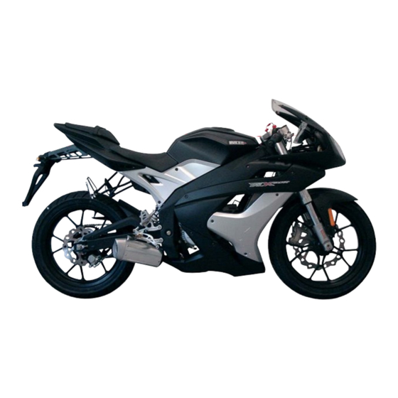
Page 8: Motorbike Parts - Left Side
MOTORBIKE PARTS - LEFT SIDE Mirrors / Indicators. Digital apron. Fuel tank. Left-hand controls. Seat. Pillion passenger seat. Rear foot rests. Drive chain. Side stand. Gear pedal. Front brake disc. Headlamp. -
Page 9: Motorbike Parts - Right Side
MOTORBIKE PARTS - RIGHT SIDE Right-hand controls. Rear brake pedal. Exhaust pipe. Rear brake disc. Number plate support. Rear light. Indicators. -
Page 10: Handlebar Instruments
HANDLEBAR INSTRUMENTS LADO DERECHO Depósito líquido de freno delantero. Palanca freno delantero. Empuñadura acelerador. Pulsador encendido eléctrico. LADO IZQUIERDO Maneta embrague. Pulsador acústico. Conmutador luces. Conmutador intermitentes. Palanca estárter. Empuñadura izquierda. - Page 11 DASHBOARD The dashboard provides information about the status of the dri- ving parts. Full or dipped beam indicator. Indicator light indicator. Digital clock. Speedometer in kilometres per hour. Apron configuration or adjustment (SET button). Apron configuration or adjustment (MODE button). Partial kilometre clock.
- Page 13 CHECKLIST Perform the checks on the list to guarantee the correct condition of your motorbike. PART CHECK The steering should be smooth. Steering The movement should be flexible. There should be no play. Lights All the lights (Headlamp - Rear light - Brake light Indicators - Dashboard).
- Page 14 CHECKLIST PART CHECK Dashboard All the dashboard indicators. Accelerator grip The play on the grip. The acceleration and deceleration should be smooth. Tyres Pressure. The depth of the tread should be sufficient. There should be no breakages or cuts. Hooter It should sound.
-
Page 16: Ignition Lock
IGNITION LOCK The lock is located in the centre of the plate that holds the handlebar in place. It controls the ignition of the motorbike, the lighting and indicator system and the blocking of the handlebar. 1) In this position, the electric circuits are disconnected. 2) The electric circuits are activated. -
Page 17: Electric Starter Button
ELECTRIC STARTER BUTTON To start up the motorbike, use the button (1) and turn the accelerator grip towards you. IMPORTANT When the motorbike has been started up, release the button. ACCELERATOR GRIP Turn the accelerator grip backwards to accelerate and forwards to decele- rate. -
Page 18: Light Switch
HOOTER The button (1) is located on the dashboard on the left handlebar. Press the button to use the hooter. WARNING Remember that its use is particularly prohibited near hospitals and health centres. LIGHT SWITCH The light switch has two positions: 1. -
Page 19: Indicator Switch
INDICATOR SWITCH Three-position indicator switch: 1) Left indicators. 2) Indicators off. 3) Right indicators. Turn the switch to the right or to the left and press it to turn it off. CHOKE LEVER Press the lever (1) as far as possible to start up the motorbike in cold weather. -
Page 20: Clutch Lever
CLUTCH LEVER The clutch is operated using a lever (1) on the left handlebar. Use it to engage and declutch the engine gears. Press the lever (1) to declutch and release it gently to engage a gear. FRONT BRAKE LEVER The front brake is operated using a lever (1) on the right handlebar. -
Page 21: Gear Pedal
GEAR PEDAL The pedal (1) is on the left side of the motorbike next to the engine. Press the pedal (1) down with your toes to engage first gear. Place your foot under the lever (1) and push it up for the remaining gears. The pedal (1) will return to its initial position after a gear has been engaged. -
Page 22: Rear Brake
REAR BRAKE The rear brake is applied using a pedal (1) located on the right side of the motorbike next to the engine. Press the lever gently with your toes. WARNING Use the brake in accordance with the road surface and weather conditions. REAR FOOT RESTS Located at the rear of the bike. - Page 23 FUEL TANK CAP To open the petrol tank, proceed as follows: 1) Lift the cover (1) that protects the lock. 2) Insert the key (2) in the lock and turn it 90° to the left. 3) Lift the cap (3) to remove it from the tank. To close the petrol tank cap, proceed as follows: 1) Insert the cap (3) in the tank inlet.
-
Page 24: Opening And Closing The Seat
OPENING AND CLOSING THE SEAT To open the seat, proceed as follows: 1) Remove the two bolts, one on each side, that secure the seat to the chassis. The two bolts are housed in the holes (a) located under the seat. 2) Pull the seat up and back. -
Page 25: Opening And Closing The Pillion Passenger Seat
OPENING AND CLOSING THE PILLION PASSENGER SEAT To open the seat, proceed as follows: 1) Insert the key in the lock and turn it 90° to the right. 2) Pull the seat up and back. To close the seat, proceed as follows: 1) Position the central tab (1) under the flap (2). -
Page 26: Blocking And Unblocking The Handlebar
BLOCKING AND UNBLOCKING THE HANDLEBAR To block the handlebar, proceed as follows: 1) Turn the handlebar to the left. 2) Insert the key, press it (1) and release. 3) Then turn the key to the left (2) and remove it. To unblock it, proceed as follows: 1) Insert the key and turn it to contact or standby position. -
Page 27: Side Stand
SIDE STAND The stand is located on the left side of the bike. 1) Lean the bike a little to the right. 2) Use your foot to push the stand to the ground. 3) Then rest the bike on the stand. To unblock it, proceed as follows: 1) Lean the bike a little to the right. -
Page 29: Front Headlight - Main Beam/Dipped Beam Bulb
FRONT HEADLIGHT – MAIN BEAM/DIPPED BEAM BULB To renew the main beam/dipped beam bulb, proceed with the following steps: 1) Turn the bulb holder (1) to the left and withdraw it. 2) Press the clip (2) holding the bulb (3) and withdraw it. WARNING Keep the ignition disconnected during this operation. -
Page 30: Front Turn Indicators
FRONT TURN INDICATORS To renew the turn indicator bulbs, proceed with the following steps: 1) Loosen the screw (1) holding the screen (2). 2) Withdraw the screen (2). 3) Press and turn the bulb (3) to the left to withdraw it. WARNING Keep the ignition disconnected during this operation. -
Page 31: Rear Turn Indicators
REAR TURN INDICATORS To renew the turn indicator bulbs, proceed with the following steps: 1) Insert a screwdriver (1) into the bottom hole and lever off the screen (2). 2) Press and turn the bulb (3) to the left to withdraw it. WARNING Keep the ignition disconnected during this operation. -
Page 32: Rear Light
REAR LIGHT To replace the rear light, proceed as follows through the rear wheel space: 1) Disconnect the lamp from the cables (1). 2) Hold the lamp with one hand. 3) Remove the two screws (2) and remove the light. WARNING Keep the ignition disconnected during this operation. -
Page 33: Number Plate Light
NUMBER PLATE LIGHT To replace the number plate light bulb, proceed as follows: 1) Tire del portalámparas(1) y retírela la bombilla(2). WARNING Keep the ignition disconnected during this operation. PRECAUTION Do not pull on the cables to disconnect the bulb. MIRRORS Check the view through the rear view mirrors and adjust if necessary: 1) Press the rear view mirror glass (1) to position it correctly. -
Page 34: Front Brake
FRONT BRAKE To increase or reduce the tensioning of the front brake: 1) Loosen the fastening nut (1). 2) Use a No. 4 Allen key (2) to increase or reduce the action of the front brake. 3) Use the fastening nut (1) to secure it in position. REAR BRAKE To increase or reduce the tensioning of the rear brake: 1) Loosen the fastening nut (1). - Page 35 ACCELERATOR GRIP To increase or reduce the sensitivity of the grip: 1) Remove the protective rubber (1). 2) Loosen the fastening wheel (3). 3) Move the wheel (2) to tighten or loosen the cable. 4) Use the fastening wheel (3) to secure it in position. CLUTCH LEVER To increase or reduce the tensioning of the clutch: 1) Remove the protective rubber (1).
- Page 36 BATTERY First the seats need to be removed (Page. 34 and 35). 1) Remove the 4 screws (1) that secure the cover. 2) Disconnect the two connection cables. Negative -(2) - Positive (3). WARNING Take the old battery to your distributor for recycling. PRECAUTION If you replace the battery, make sure that the new battery does not exceed 12 V and 6 Ah.
-
Page 37: Lubricating Oil
LUBRICATING OIL Before carrying out this operation, turn off the engine. First the pillion passenger seat needs to be removed (Page 35) 1) Remove the cap(1). 2) Top up if necessary. Recommended oil: SAE 10W30 COOLANT Before carrying out this operation, turn off the engine. 1) Remove the cap(1). -
Page 38: Air Filter
AIR FILTER First the two seats and the battery cover need to be removed (Pages 34, 35 and 48). 1) Remove the 6 bolts (1) that hold the filter cover in position. 2) Remove the cover (2) by pulling it up. 3) Remove the filter (3) by pulling it up. -
Page 39: Crankcase Oil Level
CRANKCASE OIL LEVEL Before carrying out this operation, remove two plastic side panels. 1) Remove the 4 screws (1) from the plastic side panel (2) and remove it. 2) ) Remove the 3 screws (3) indicated, to access the plug. 3) Withdraw the plug (4). -
Page 40: Front Brake Fluid
FRONT BRAKE FLUID The brake fluid reservoir is next to the right handlebar. The reservoir has a sight glass (1) to see the level of the fluid. Check that the level is correct. If it is not correct, proceed as follows: 1) Loosen the two bolts (2) on the cap. -
Page 41: Rear Brake Fluid
REAR BRAKE FLUID The brake fluid reservoir is located above the lever. En el depósito encontrará una mirilla(1) para visualizar el nivel del líquido. Compruebe que el nivel es el apropiado. Si no es así, realice los siguientes pasos: 1) Remove the two bolts(2) and place the tank vertically. 2) Loosen the two bolts (4) on the cap (3). -
Page 42: Front Wheel
FRONT WHEEL 1) Loosen the bolt(1) on the right fork that holds the axle in position(2). 2) Remove the nut(3) on the left side of the wheel axle(2). 3) Remove the axle from the wheel until the separator is released(4). 4) Hold the wheel and remove the axle (2) until it is released. -
Page 43: Rear Wheel
REAR WHEEL 1) Loosen the 2 nuts (1) that hold the rear wheel axle in position. 2) Loosen the chain tensioning fastening nut (2). 3) Tighten the bolt (3) as far as possible. 4) Push the wheel until the chain (5) is loose. 5) Release the chain (5) from the plate (6). -
Page 44: Tensioning The Drive Chain
TENSIONING THE DRIVE CHAIN To tension the drive chain, proceed as follows on both sides. 1) Loosen the 2 nuts (1) that hold the rear wheel axle in position. 2) Loosen the fastening nut (2). 3) Adjust the chain tension using the bolt (3). 4) The chain (4) should have a tolerance of approximately 30mm. -
Page 45: Dashboard Configuration Or Adjustment
DASHBOARD CONFIGURATION OR ADJUSTMENT The instrument panel has two adjustment buttons: SET(1) button and MODE(2) button. Aim of the buttons is: Allow functions scrolling. Regulation of the clock. Set to zero the TD, AVE , LAP and MAX values. Entering the Set-up menu to modify the wheel cir- cumference value, the measurement unit value of distance, the number of impulses for every turn of the wheel and of the engine, and finally to associate the... - Page 46 The function scrolling is always possible (it means the passage from one function to the following one) with the vehicle stopped or not. To update the instrumentation with the new function, it’s enough briefly pushing the button (tmin = 1 sec.), when it will be left the display will show the new function.
- Page 47 Totalizer function (TOTAL) The data is permanently memorized in a non volatile memory (E refresh every km). If the memory is empty You’ll see numbers 00000 visualised. This information is always calculated in km. Anyway it must be expressed in km or mph. You can select the chosen information by entering the Set-Up menu.
- Page 48 Trip function (TD) This function describes the correct working/visualization of the board au- tomatic partial totalizer. The visualized data represents the vehicle covered distance expressed in miles or km (depending on the selected measurement unit), with resolu- tion 0.1 (miles or km). This counter is automatic: in fact it automatically starts with the first pulse arriving from speed sensor.
- Page 49 Time Function (TIME) This function describes the correct working/visualization of the current hour. This function is always shown in the format hh:mm, by using di- git 1-4. Clock is active also when the microcontroller is in sleep mode phase and regulation of the hour can be done only when the vehicle is stopped.
- Page 50 Time parameter will be shown in 0-24 format if unit of measurement chosen is km/h, while it will be shown in 0-12 format if unit of measure- ment is mph. In this case on the display You will see on 5 and 6 digits the logo “AM”...
- Page 51 Automatic Chronometer Function (LAP) This function describes the correct working/visualization of the chrono- meter related to TD and AVE. This information is visualized by using digit 13-16 and logo LAP . The data represents the effective route time of the vehicle in the form mm:ss if hours = 0 and in the form hh:mm if hours >...
- Page 52 Average speed function (AVE) This function describes the correct working/visualization of average speed function related to TD and LAP . The data represents the average speed of the vehicle (expressed in Km/h or in Mph depending on the selected measurement unit) that is calculated as ratio between covered distance (TD) and the time used to cover this distance (LAP).
- Page 53 Max. speed function (MAX) This function describes the correct working/visualization of maximum speed function. The information is visualized by using digit 14-16 and logo MAX. The parameter identifies the maximum speed achieved by the vehicle, expressed in km/h or mph depending on the selected unit of measu- rement.
-
Page 54: Alarms Management
ALARMS MANAGEMENT Battery voltage alarm Every time that found out voltage value goes down 9,5V, the system starts alarm routine to signal the possibility that after switching ON of the vehi- cle, the speedometer can loose its settled data. The signal is the graphic bar visualization(regardless the current function), by blinking the first segment of the bar and battery symbol. - Page 55 MENÚ SETUP [CONFIG.] The entry in the set-up menu is only possible when the vehicle is estopped by pushing at the same time the Mode and the Set button for about 04 seconds regardless the visualized function. On the display the “SET Par” logo will appear fixes for the entry in the set-up menu of parameters.
- Page 56 Obserbations: Changing measurement unit will cause the conversion of TOTAL and will set to 000.0 TD. Once inside the regulation menu: if 20 sec. will pass without the button mode is pushed, or if the vehicle is turned on (speed>0), or if the key is turned OFF the system will be automatically taken to the standard operating mode and the modifications possibly produced will be lost.
-
Page 58: Maintenance Checklist
MAINTENANCE CHECKLIST PART 1.000 Km 6.000 Km (6 months) 12.000 Km (12 months) Air filter Check Clean - Change Clean - Change Lights Check - Adjust Check Check Engine crankcase oil Change Check Change Lubricating oil Check - Refill Check - Refill Check - Refill Brake fluid Check - Refill... -
Page 60: Troubleshooting
TROUBLESHOOTING The following is to help in the event of possible problems: THE ENGINE DOES NOT START The fuel tank is empty. The sparkplug is dirty. The sparkplug does not produce a spark. The carburettor is flooded. THE ENGINE DOES NOT START UP IMMEDIATELY The sparkplug is dirty or in poor condition. - Page 61 TROUBLESHOOTING LACK OF POWER The exhaust pipe is dirty. The silencer is dirty. The air filter is dirty. THE CLUTCH SLIPS Insufficient play in the clutch control. Insufficient tensioning of the clutch spring. The clutch discs are worn. THE BRAKES DO NOT WORK CORRECTLY Pads are worn.
- Page 63 ENGINE MINARELLI AM 6 CYLINDER CAPACITY 49.7cc COOLING water START electric IGNITION electric by CDI DIAMETER X STROKE 40.3mm X 39.0mm COMPRESSION RATIO 12:1 CLUTCH Multi-disc bathed in oil CARBURETTOR Dell’Orto PHBN 16 CHASSIS double steel frame FRONT SUSPENSION 41mm inverted fork, Paioli advanced axle REAR SUSPENSION Ollé...
Need help?
Do you have a question about the RX 50R and is the answer not in the manual?
Questions and answers