
Related Manuals for Baumfolder BAUM 2018


Summary of Contents for Baumfolder BAUM 2018
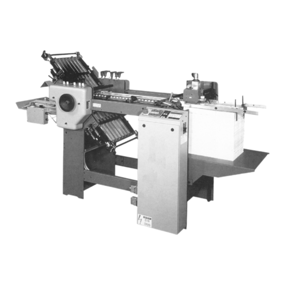
- Page 1 BAUMFOLDER BAUM 2018 1ST STATION FOLDER W/PILE FEED INSTRUCTION MANUAL ©Baumfolder Corp., 1999 Printed in U.S.A. TP10313 PAGE 1 TP10313...
- Page 2 WARNING FOLDER IDENTIFICATION TP10313 PAGE 2...
-
Page 3: Table Of Contents
CONTENTS DESCRIPTION PAGE Safety ................................. 6 II.) Warning Labels ..............................7 III.) Introduction Overview ............................ 8 IV.) Transportation/Installation ..........................8 Squaring the Machine ............................. 8 VI.) Electrical Connections ............................ 9 VII.) Installing Fold Plates & Stacker Delivery ....................10 VIII.) Operator Controls ............................ -
Page 4: Description Page
CONTENTS DESCRIPTION PAGE IX.) Pile Feeder Operation ............................ 26 Register Operation ............................28 XI.) Baumset Adjustment ............................29 XII.) Setting Fold Plates ............................30 XIII.) Setting Deflectors ............................30 XIV.) Stacker Operation ............................31 XV.) Scoring/Slitting/Perforating .......................... 32 XVI.) Lubrication/Maintenance ..........................36 XVII.) Technical Specifications .......................... - Page 5 List of Tables DESCRIPTION PAGE PAGE 5 TP10313...
-
Page 6: Safety
SAFETY FIRST Be sure to follow these safety precautions: Additional Notes: TP10313 PAGE 6... -
Page 7: Ii.) Warning Labels
WARNING LABELS WARNING WARNING GUARD MISSING GUARD MISSING DO NOT OPERATE DO NOT OPERATE 50944 50945 CAUTION – HAZARDOUS MOVING PARTS – GUARDS MUST BE IN PLACE WHEN OPERATING FOLDER – KEEP HANDS, HAIR & LOOSE ARTICLES AWAY FROM MOVING PARTS. 50215 CAUTION - HAZARDOUS MOVING PARTS DO NOT OPERATE MACHINE... -
Page 8: Iii.) Introduction Overview
INTRODUCTION OVERVIEW SQUARING THE MACHINE Figure 3 Figure 1 TRANSPORTATION/INSTALLATION Figure 2 Figure 4 TP10313 PAGE 8... -
Page 9: Vi.) Electrical Connections
ELECTRICAL CONNECTIONS 1.2 Tapping the Transformer 1.0 Wiring the Pump (2018 / 1 phase) 1.1 Other Connections 1.3 Pump Connections NOTE PAGE 9 TP10313... -
Page 10: Vii.) Installing Fold Plates & Stacker Delivery
INSTALLING FOLD PLATES & STACKER OPERATOR CONTROLS DELIVERY 1.0 Setting Folding Speed 1.1 Setting Stacker Belt Speed 1.2 Emergency Stop Button Figure 7 Figure 9 BAUMFOLDER CORPORATION Figure 8 TP10313 PAGE 10... -
Page 11: Control Panel Ban-5
Control Panel BAN-5 BAUMFOLDER CORPORATION Figure 1. Control Panel. 1.1 Displays 1.3 Machine Control Pushbuttons 1.2 Machine Status Indicators PAGE 11 TP10313... -
Page 12: Run Mode Functions
2.1 Machine Setup/Diagnostic Mode 1.4 Keypad Buttons with Selection Indicators 1.5 Keypad Buttons for Selection Adjustment Parameter Group Selection Parameter Selection within a Group 2.0 Run Mode Functions Select Parameter Adjustment During the self test operation, do not press any button. - Page 13 2.1.1 Machine Setup Parameters Parameter Function Type Variable Displayed Table 1. Machine Setup Parameter List P02: Tremat P00: Input Factor P03: Knife P01: Output Factor 2.1.2 Machine Monitor Parameters Function Type Variable Displayed Table 2. Machine Monitor Parameter List P10: Machine Speed (Velocity) P14: Pause Time P11: Job Run Time P15: Job Number...
- Page 14 2.1.3 Machine Setup Parameters Function Type Variable Displayed Table 3. Machine Setup Parameter List P25: Easy Mode P20: Units of Measurement P21: Language P26: Hardware and Firmware Version P22: Network Address P27: Machine Type P23: Pause P24: Network Enable P28: Serial Output Type TP10313 PAGE 14...
- Page 15 P28: Serial Output Type 2.1.4 Diagnostic Parameters Table 4. Machine Diagnostic Parameter List P30: Input Port 1 Status P31: Input Port 2 Status P34: Output Port 1 Status P32: Input Port 3 Status P35: Output Port 2 (Extension) P33: Input Port 4 Status (Extension) 2.1.5 Future Features Function Type...
- Page 16 2.1.6 Machine UsageStatus Parameters Function Type Variable Displayed Table 6. Machine Usage Status Parameter List P50: Power On Time P51: Machine Run Time P52: Total Input Sheets Future Feed Interruption Speed Up Table MKE Table Kicker Feature Available Frame Frame Frame Frame Frame...
- Page 17 Batching Time Adjustment Select Continuous Cycle Mode Select Count Source The batching count source will be the feeder photoeye. The batching count source will be whatever is connected as the delivery photoeye. 2.4 Learn Mode Table 8. Count Source Selection 2.3 Easy Mode and Continuous Cycle No valid sheet has been read yet, the system is in Mode...
- Page 18 Select Suction Mode Gap Length Adjustment Suction Length Adjustment Sheet Length Adjustment TWT-180 Mode Leading Edge Control Leading and Trailing Edge Control Table 10. Suction Mode Symbols Sheet Length Setting Resultant Suction Length Percentage Table 11. Suction Length Function 2.5 Make Ready Mode TP10313 PAGE 18...
- Page 19 2.7 Production Mode 2.6 Network Job Mode Large Display Contents Output Count Batch Count Down Number of Batches Current Rate Input Count Select Job Number Waste Count Table 12. Determining the Large Display Contents Gap Length Adjustment Suction Length Adjustment PAGE 19 TP10313...
-
Page 20: Logic Board Status Indicators
Reset Function Reset while showing Output Count will reset all job variables. Reset while showing batch data will reset Number of Batches and reload the Batch Down Count. Table 13. Reset mode Selection 3.0 Logic Board Status Indicators Reference Name Description Designator Table 14. -
Page 21: Process Variables Definitions
4.0 Process Variables Definitions 4.1 Total Input Count 4.6 Main Drive Run Time 4.2 Total Output Count 4.7 Main Drive Velocity 4.3 Batch Down Count 4.8 Waste Count (Option) 5.0 Counter Setup Variables 5.1 Batch Preset 4.4 Number of Batches 5.2 Batch Output Type 4.5 Current Rate PAGE 21... - Page 22 5.3 Batch Output Time Output Delay Duration Type Min. Time Max. Time Min. Time Max. Time Table 15. Output Delay and Duration 5.4 Sheet Length 5.5 Gap Length 5.6 Suction Length TP10313 PAGE 22...
-
Page 23: System Messages And Run Messages
6.0 System Messages and Run Messages 6.1 Power-Up Fault Messages ENGLISH GERMAN CODES TYPE DESCRIPTION Action Action Action Action Action Action Action Table 16. Power Up Fault Messages PAGE 23 TP10313... - Page 24 6.2 Run Time Fault Messages ENGLISH GERMAN CODES TYPE DESCRIPTION Action Action Action Action Action Action Table 17. Run Time Fault Messages TP10313 PAGE 24...
- Page 25 6.3 Machine Run Error Messages ENGLISH GERMAN CODES TYPE DESCRIPTION ACTION ACTION ACTION ACTION ACTION ACTION ACTION ACTION ACTION Table 18. Machine Run Error Messages PAGE 25 TP10313...
- Page 26 PILE FEEDER OPERATION 1.0 Loading the Pile Feeder Figure 11 1.2 Hold-down Locations Figure 12 1.3Air and Vacuum Settings Figure 13 Figure 14 TP10313 PAGE 26...
- Page 27 1.3 FRONT BLOW TUBE SETTINGS Setting Up Figure 16 1.4 Vacuum Wheel Figure 17 Figure 15 PAGE 27 TP10313...
- Page 28 Figure 18 REGISTER OPERATION Figure 20 1.0 DOUBLE SHEET DETECTOR Figure 19 TP10313 PAGE 28...
- Page 29 Figure 21 BAUMSET ADJUSTMENT 1.0 Adjustment of Folding Rollers Figure 22 PAGE 29 TP10313...
- Page 30 SETTING OF FOLD PLATES NOTE: CAUTION: SETTING OF SHEET DEFLECTORS CAUTION: Figure 23 Figure 24 Figure 25 TP10313 PAGE 30...
- Page 31 Setting Stationary Deflector NOTE: Figure 26 STACKER (DELIVERY) Figure 27 Figure 28 PAGE 31 TP10313...
- Page 32 SCORING/SLITTING/PERFORATING 1.1 Scoring 1.0 Slitter Shaft Accessories Removal Figure 31 Figure 29 Figure 30 Figure 32 TP10313 PAGE 32...
- Page 33 1.2 Perforating Figure 33 Figure 34 Perforator Blades Part # Description Figure 35 PAGE 33 TP10313...
- Page 34 1.3 Slitting (Cutting) Sheets Figure 36 Slitter Blades Part # Description Figure 37 TP10313 PAGE 34...
- Page 35 1.4 Trimming Edges of Booklets Trimming a Strip from Center of Sheet Figure 38 Figure 39 PAGE 35 TP10313...
- Page 36 LUBRICATION/MAINTENANCE Pile Feeder Figure 40 Register Folder WARNING: WARNING: Figure 41 TP10313 PAGE 36...
- Page 37 TECHNICAL SPECIFICATIONS BAUM 2018 ACCESSORIES PAGE 37 TP10313...
- Page 38 TROUBLESHOOTING PROBLEM CAUSE REMEDY TP10313 PAGE 38...
- Page 39 TROUBLESHOOTING - continued PROBLEM CAUSE REMEDY PAGE 39 TP10313...
- Page 40 OPERATING TIPS Setup TIPS FOR FOLDING Brass Tipped Screws Roller Setting for Accordian and Letter Folding Static Electricity Processing Thin Printing Stock Cutting Blade Wear Folding Roller Adjustment Measuring Odd Thirds Paper Grain in Letter Folds Pull-out Bands Using Guide Marbles Slitter Shaft Setup TP10313 PAGE 40...
- Page 41 Fixing Crooked Perforations Bottom Plate Lip Adjustment Figure 43 Figure 44 Figure 42 Figure 45 Figure 46 PAGE 41 TP10313...
- Page 42 Principles of Mechanical Folding The buckle folding principle Figure 49 Figure 50 Figure 51 Figure 47 Figure 52 Figure 48 TP10313 PAGE 42...
- Page 43 DEFLECTOR OPEN SHEET STOP MAIN DRIVE DEFLECTOR OPEN DEFLECTOR CLOSED DEFLECTOR CLOSED SHEET STOP IMPOSITIONS 18 MOST POPULAR FOLDS PAGE 43 TP10313...
- Page 44 On a buckle folder, the sheet is laid flat on a register table and then enters the fold pan assembly where it comes to a stop against the stationary fold plate stop. A series of buckles then forms throughout the sheet. The buckles whithin the fold pan are kept very small by the narrow channel design. The buckles at the end of the fold pan, however, will be larger.
- Page 45 On the next page is a quick explanation of the basic theory of buckle folding. Although reasonable care has been taken to assure accuracy, Baumfolder Corporation does not assume any respon- sibility for any errors that might inadvertently be contained in this manual. When trying a new fold, it is always advisible to set up a test run to check for potential problems.
- Page 46 TYPICAL LAYOUT AND SHEET ORIENTATION Each numbered Imposition Block in this manual contains: A. Imposition Title B. Fold Pans Used C. Sheet Layout D. Folded Sample SIDE GUIDE 2. Dashed lines represent folds. Page numbers or letters without circles are face up. Page numbers or letters with circles are on the underside of the sheet.
- Page 47 4-PAGE 4-PAGE, DOUBLE 6-PAGE, STANDARD IMPOSITION 6-PAGE, ACCORDION 8-PAGE, PARALLEL 8-PAGE, RIGHT ANGLE IMPOSITION PAGE 47 TP10313...
- Page 48 8-PAGE, TWO RIGHT 8-PAGE, RIGHT 8-PAGE, PARALLEL ANGLE OBLONG ANGLE DOUBLE OVER & OVER IMPOSITION 12-PAGE BOOK, 12-PAGE BOOK, 12-PAGE LETTER SADDLE STITCH SADDLE STITCH FOLD, HEADS OUT TP10313 PAGE 48...
- Page 49 12-PAGE LETTER 12-PAGE LETTER 16-PAGE, THREE FOLD, HEADS IN FOLD, ACCORDION RIGHT ANGLE BOOK IMPOSITION 12-PAGE FOLDER, 24-PAGE BOOKLET 32-PAGE BOOK HEADS OUT PAGE 49 TP10313...
- Page 50 Baumfolder has authorized dealers located through- out the United States. Call toll free, 1-800/543-6107 for parts or the number of your nearest authorized dealer. BAUMFOLDER Producing Bindery Equipment Since 1917 TP10313 PAGE 50...
Need help?
Do you have a question about the BAUM 2018 and is the answer not in the manual?
Questions and answers