Roland A-37 Owner's Manual
Midi keyboard controller
Hide thumbs
Also See for A-37:
- Owner's manual (28 pages) ,
- Midi implementation manual (6 pages) ,
- Features (1 page)
Table of Contents
Advertisement
Quick Links
Download this manual
See also:
Owner's Manual
Sept, 2001
a-37
midi keyboard
controller
TABLE OF CONTENTS
SN00053
K6018448
A-37
SERVICE NOTES
Second edition
Issued by RES
Page
1
2
3
4
5
6
6
6
9
10
10
11
12
12
13
14
15
Printed in Italy (I00) (AD)
1
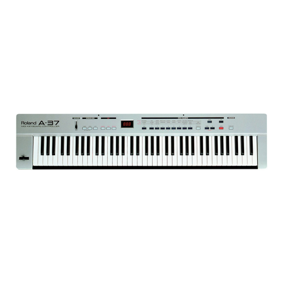
Specifications
Keyboard: 76 keys, velocity sensitive, with channel Aftertouch
Display: 3 x 7 segments
Realtime controllers: Data Entry slider, Bender/Modulation lever, channel Aftertouch, Hold Foot Switch socket, Foot Pedal socket
Memories: 128 Patches
Connections: MIDI In, Out A, Out B, Thru, Expression Pedal, Sustain Footswitch, DC IN (adaptor)
Compatibility: GM/GM2/GS, all MIDI messages
Power supply : Batteries, AC/DC adaptor (DC 9V)
Dimension: 1195 (W) x 270 (D) x 113 (H) mm
Weight:: 7,7 Kg
Supplied accessories: 6 x dry batteries (AA type), MIDI cable, Owner's Manual, Music Rest
Options: Roland ACA adaptor (9V, 200mA); DP-2, DP-6, or BOSS FS-5U footswitch; EV-5, Boss FV-300L expression pedal
Specifications subject to change without prior notice. All other trademarks mentioned in this manual are the property of the respective companies.
DISASSEMBLY
SILKSCR. BOTTOM CABINET ASSY REMOVAL SCREW x10 Pcs
SELF TAP. SCREW 3,5x16 TCTCPRBZ
Cod. J2289131
Copyright © 2001 by ROLAND CORPORATION
All rights reserved. No parts of this publication may be reproduced in any form whithout the written permission of ROLAND CORPORATION.
Advertisement
Table of Contents

Related Manuals for Roland A-37


Summary of Contents for Roland A-37
-
Page 1: Table Of Contents
SELF TAP. SCREW 3,5x16 TCTCPRBZ Cod. J2289131 Copyright © 2001 by ROLAND CORPORATION SN00053 K6018448 Printed in Italy (I00) (AD) All rights reserved. No parts of this publication may be reproduced in any form whithout the written permission of ROLAND CORPORATION. -
Page 2: Location Of Controls
A-37 Sept, 2001 LOCATION OF CONTROLS REAR VIEW... -
Page 3: Exploded View
A-37 Sept, 2001 EXPLODED VIEW... -
Page 4: Keyboard Parts List
A-37 Sept, 2001 KEYBOARD PARTS LIST 76 KEY KEYBOARD TP/9-AT Code: 7772109000 PARTS NAME PARTS NUMBER n. KEY SPRING gr.63 J2179101 NATURAL KEY C5 (gr.10) J2579112 NATURAL KEY D6 (gr.10) J2579113 NATURAL KEY E7 (gr.10) J2579114 NATURAL KEY F1 (gr.10) J2579115 NATURAL KEY G2 (gr.10) -
Page 5: Parts List
(INTERF.DRIVER IC) IC3 on LCB 15289141 I.C. M5223FP-600D IC12 on CPU 12209532RI BATTERY HOLDER FOR 6 BATTERIES 7772104000 I.C. MICRO CONTR.IC2 CPU (PROGRAM.) A-37 IC2 on CPU 22365708 HOLDER F/POWER SUPPLY CBL 13429823RI P. SUPPLY PLUG LOCKING TRANSISTOR ACCESSORIES 15319101... -
Page 6: How To Visualize The System Program Version
After a few seconds, the display will visualize the following writing: If you exit the test before checking all the buttons, the display indicates the name of the untested TEST ROLAND A - 37 VERSION 1.00 buttons. Press EXIT to go back to the main menu. - Page 7 A-37 Sept, 2001 Press EXIT to leave. If you press the pedal, the display visualzes the status (ON) of the pedal (Pict. A); when you release Press EXIT again to go back to the main menu. the pedal, the display visualizes its new status (OFF) (Pict. B).
- Page 8 A-37 Sept, 2001 Note: When carring out this test, make sure you press the key properly. In case a key does not reack 127, try pressing a few other keys. In any case, a tolerance 08-10% is acceptable. Press EXIT to leave.
-
Page 9: Block Diagram
A-37 Sept, 2001 BLOCK DIAGRAM BEND-MOD UNIT JACK BOARD CONTROL BOARD CPU BOARD SUSTAIN M38039FFFP SWITCH DATA AN0-AN2 ENTRY 16MHz P10-P13 EXPRESSION PEDAL DISPLAY XOUT XOUT P20-P27 RESET XRES P50-P52 IC10 MATRIX INT1 XINT 10MHz Q1-Q4 KEYSCAN BUFFER P00-P07 LATCH... -
Page 10: Jack Pcb Assy & Circuit Diagram
A-37 Sept, 2001 JACK PCB ASSY & CIRCUIT DIAGRAM ASSY 7697603000 HLJ_0520_01_110 SUSTAIN SWITCH 6 WIRE CABLE P2.5 SBT0160W SUST DGND DGND EXPJ From CPU Board (CN5) SBT0160W 470K EXPRESSION PEDAL HLJ_0520_01_010 View from component side CPU PCB ASSY ASSY... -
Page 11: Circuit Diagram (Cpu Pcb Assy)
A-37 Sept, 2001 CIRCUIT DIAGRAM (CPU PCB ASSY) +5VD +5VD 4x10Ks DIVEN SSD0 100nFs +5VD SSD1 +5VD SSD2 SSD3 8x10Ks 22Ks 220s DA204K 3K3s XINT FOR BUILT-IN FLASH YKF515054 RSVD +5VD PROGRAMMING SBT0160W C_1_27_2510_6002_UN TO LEFT CONTROL BOARD TO LEFT CONTROL BOARD... -
Page 12: Power Supply Pcb Assy & Circuit Diagram
A-37 Sept, 2001 POWER SUPPLY PCB ASSY & CIRCUIT DIAGRAM ASSY 7772105000 6 WIRE CABLE P2.5 To CPU Board (CN8) TN6717A HEC047001630 PLT1R53C SSSP12114A DC IN 9V 100nFC 47uF16 100nFC 1N4001 100uF16 BATTERY BZX79C5V6 (MN1500 6 pcs) CONN_2X1 10uF16 10uF16... -
Page 13: Circuit Diagram (Left Control Pcb Assy)
A-37 Sept, 2001 CIRCUIT DIAGRAM (LEFT CONTROL PCB ASSY) TO RIGHT CONTROL BOARD (CN1) DRW0 220I SSD3 DRW7 SSD2 DRW6 SSD1 LOWER SSD0 DRW1 220I UPPER 14 WIRE CABLE P1.27 DRW2 DISPLAY 3X7 SEGMENTS 220I DRW0 SPLIT DRW1 DRW2 DRW3... -
Page 14: Right Control Pcb Assy & Circuit Diagram
A-37 Sept, 2001 RIGHT CONTROL PCB ASSY & CIRCUIT DIAGRAM ASSY 7772101000 View from component side DRW6 TRANSPOSE DRW7 AMPC1_2714P START/STOP SSD3 DRW7 SSD2 DRW6 SSD1 SSD0 ENTER WRITE FROM LEFT CONTROL BOARD (CN1) SSD0 DOWN SSD1 START/STOP SSD2 TRANSPOSE... -
Page 15: Right & Left Contact Pcb Assy & Circuit Diagram
A-37 Sept, 2001 LEFT CONTACT PCB ASSY w/RUBBER ASSY 7695005000 View from component side RIGHT CONTACT PCB ASSY w/RUBBER ASSY 7695004000 View from component side CIRCUIT DIAGRAM (LEFT CONT.PCB ASSY) CIRCUIT DIAGRAM (RIGHT CONT.PCB ASSY)
Need help?
Do you have a question about the A-37 and is the answer not in the manual?
Questions and answers