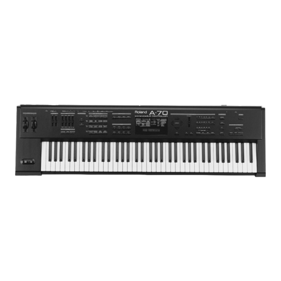
Roland A-70 Service Manual
Expandable controller
Hide thumbs
Also See for A-70:
- Owner's manual (73 pages) ,
- Service notes (27 pages) ,
- Midi implementation manual (16 pages)
Table of Contents
Advertisement
Quick Links
Sept, 1997
TABLE OF CONTENTS
SPECIFICATIONS
EXPLODED VIEW N.1
EXPLODED VIEW N.2
SN00018
K6018299
A-70
SERVICE NOTES
First Edition
Issued by RES
Page
1
1
2
3
4
4
5
6
7
8
8
9
10
10
11
12
12
13
14
14
15/20
20/21
22/27
Printed in Italy (AF00) (AD)
1
S P E C I F I C AT I O N S
A-70/A-70EX : Expandable controller
A-70EX Sound Section (VE-RD1)
- Sound Generator
PCM synthesis
- Parts
4 Parts
- Maximum Polyphony
64 Voices.
- Effects
Reverb
Chorus
Equalizer
- Preset Memory
Patches
A-70/A-70EX Common
- Keyboard
76 Keys
- Zones
Internal
- Internal Memory
Performances
- Display
3 Characters (backlit LCD)
17 Characters, 2 Lines (backlit LCD)
.- Nominal Output Level
Output
- Output Impedance
Output
- Recommended Load Impedance
Output
- Connectors
Midi Connectors (in:2, thru:1, out:4)
Foot Controller Jacks:1
Switch Jacks:1
Total Volume Pedal Jack
Hold Pedal Jack
Output Jacks [L(Mono), R]
Headphone Jack
- Power Supply
AC 100V, AC 117V, AC 230V or AC 240V
- Power Consumption
15W (AC 100V), 17W (AC 117V)
20W (AC 230V), 20W (AC 240V)
- Dimensions
1245(W) X 357 (D) X 136 (H) mm
- Weight
16 Kg
- Accessories
Pedal Switch:DP-2
!
!
!
!
!
- Options
Stereo Headphone
Pedal Switch
Expression pedal
Connecting Cable
MIDI/SYNC cable
Voice Expansion board
DISASSEMBLY
Copyright © 1997 by ROLAND CORPORATION
: 128
: 4
: 4
: 1
: 4
: 9
: 64
: 10
: 1
: -7dBm.
: 1600 Ohm.
: 10 Kohm or Greater
(7710610000)
(K6018288)
(K6018291)
230V
(J3439150)
117V
(J3439128)
100V
(13499108)
230VE
(13499152RI)
240VA
(13499150RI)
: RH-20/80/120:
: DP-2/6, BOSS FS 5U
: EV-5
: PJ-1M, PCS-100PW
: MSC-15/25/50
: VE series
Advertisement
Table of Contents

Related Manuals for Roland A-70


Summary of Contents for Roland A-70
-
Page 1: Table Of Contents
Pedal Switch : DP-2/6, BOSS FS 5U Expression pedal : EV-5 Connecting Cable : PJ-1M, PCS-100PW MIDI/SYNC cable : MSC-15/25/50 Voice Expansion board : VE series DISASSEMBLY Copyright © 1997 by ROLAND CORPORATION SN00018 K6018299 Printed in Italy (AF00) (AD) -
Page 2: Location Of Controls & Rear View
A-70 Sept, 1997 LOCATION OF CONTROLS & REAR VIEW... -
Page 3: Exploded View N.1
A-70 Sept, 1997 EXPLODED VIEW N.1... -
Page 4: Keyboard Parts List
A-70 Sept, 1997... -
Page 5: Block Diagram
A-70 Sept, 1997 BLOCK DIAGRAM... -
Page 6: Main Pcb Assy
A-70 Sept, 1997 For Nordic Countries MAIN PCB ASSY Apparatus containing Lithium batteries ASSY 7699501000 ADVARSEL! ADVARSEL! VARNING! VAROITUS! Lithiumbatteri - Eksplosionsfare ved Lithiumbatteri - Eksplosjonsfare. Eksplosionsfara vid felaktigt batteribyte. Paristo voi räjähtää, jos se on fejlagtig håndtering. Ved utskifting benyttes kun batteri som Använd samma batterityp eller en... -
Page 7: Circuit Diagram (Main Pcb Assy)
A-70 Sept, 1997 MAIN PCB ASSY CIRCUIT DIAGRAM... -
Page 8: Primary Pcb Assy & Circuit Diagram
A-70 Sept, 1997 PRIMARY PCB ASSY & CIRCUIT DIAGRAM ASSY 7699506000 230V/240V ASSY 7699512000 100V/117V View from component side LEFT PCB ASSY ASSY 7699504000 View from component side... -
Page 9: Circuit Diagram (Left Control Pcb Assy)
A-70 Sept, 1997 CIRCUIT DIAGRAM LEFT PCB ASSY... -
Page 10: Aft Pcb Assy & Circuit Diagram
A-70 Sept, 1997 AFT PCB ASSY & CIRCUIT DIAGRAM. ASSY 7699507000 View from component side RIGHT PCB ASSY ASSY 7699503000 View from component side... -
Page 11: Circuit Diagram (Right Control Pcb Assy)
A-70 Sept, 1997 CIRCUIT DIAGRAM RIGHT PCB ASSY... -
Page 12: Power Pcb Assy & Circuit Diagram
A-70 Sept, 1997 POWER PCB ASSY & CIRCUIT DIAGRAM ASSY 7699502000 View from component side JACK PCB ASSY ASSY 7699505000 View from component side... -
Page 13: Circuit Diagram (Midi Pcb Assy)
A-70 Sept, 1997 CIRCUIT DIAGRAM JACK PCB ASSY... -
Page 14: Right Contact Pcb Assy W/Rubber Contact & Circuit Diagram
A-70 Sept, 1997 LEFT CONTACT PCB ASSY w/RUBBER ASSY 7695005000 View from component side RIGHT CONTACT PCB ASSY w/RUBBER ASSY 7695004000 View from component side CIRCUIT DIAGRAM (LEFT CONT.PCB ASSY) CIRCUIT DIAGRAM (RIGHT CONT.PCB ASSY) -
Page 15: Test Mode
PANEL L BOARD SW/LED BOARD IC6, 10, and BT1. PANEL R BOARD SW/LED Following this, the version and test item menu will appear, and the A-70 will wait for test items to be PANEL L BOARD IC709, 710 selected. PANEL R BOARD IC201 PANEL L BOARD CN707 <=>... - Page 16 A-70 Sept, 1997 Raise and lower the six sliders TOTAL through DATAENTRY, and check that the value changes from ê 0—10 in correspondence to the slider movements. (If there is a problem, refer to check 1.) This completes the bender settings.
- Page 17 BENDER <=> PANEL L BOARD CN708 PANEL L BOARD IC705, 707 * If a VE series unit is installed in the A-70 and the OUTPUT jack is connected to an amp, a piano sound will PANEL L BOARD CN705 <=> MAIN BOARD CN11 be heard.
- Page 18 ê * The contents of the internal memory are overwritten by any data that is received. Check that when the A-70 power is turned on, there is no pop noise from the amp and the LCD is not garbled. This procedure will save the following data to sequencer;...
- Page 19 0. As necessary, save the user memory to a sequencer. The contents of user memory will be lost during During Erase or Write, be very careful to never let the power be interrupted. In the worst case, the A-70 the software update.
-
Page 20: Parts List
NOTE : Replacement LCD Unit should be made on a unit basis. No replacements available for individual parts. Replacement only be a unit. A software update will cause the user memory of the A-70 to be lost. BENDER UNIT Thus, the following adjustments will be necessary. -
Page 21: Ac Inlet (Ac 100V, Ac 230V, Ac 240V)
A-70 Sept, 1997 15199937 I.C. M51953 BP (Flat) Reset IC IC9 on MB J3439121 6P MALE CONN. P.2 M CN706 on LB ; CN101 on JB ; CN202 on RB ; CN601 on PSB 15289116 I.C. NJM2082M Dual Op. Amplifier... -
Page 22: Translation From English Into Japanese
A-70 Sept, 1997... - Page 23 A-70 Sept, 1997...
- Page 24 A-70 Sept, 1997...
- Page 25 A-70 Sept, 1997...
- Page 26 A-70 Sept, 1997...
- Page 27 A-70 Sept, 1997...
Need help?
Do you have a question about the A-70 and is the answer not in the manual?
Questions and answers