Sign In
Upload
Download
Table of Contents
Contents
Add to my manuals
Delete from my manuals
Share
URL of this page:
HTML Link:
Bookmark this page
Add
Manual will be automatically added to "My Manuals"
Print this page
×
Bookmark added
×
Added to my manuals
Manuals
Brands
Fire Pump Manuals
Water Pump
8100 Series
Installation, operation and maintenance manual
Fire Pump 8100 Series Installation, Operation And Maintenance Manual
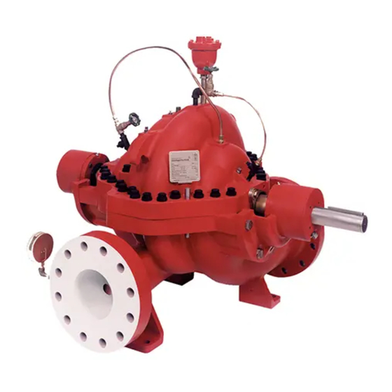
Centrifugal split case fire pumps
Hide thumbs
1
2
3
4
Table Of Contents
5
6
7
8
9
10
11
12
13
14
15
16
17
18
19
20
21
22
23
24
25
26
27
28
29
30
31
32
33
34
35
36
37
38
39
40
41
42
43
44
45
46
47
48
49
50
51
52
53
54
page
of
54
Go
/
54
Contents
Table of Contents
Troubleshooting
Bookmarks
Table of Contents
AC6102 Rev
Table of Contents
AC6102 Rev 03
1 Introduction
General
Target Group
Safety Symbols Used in this Manual
Manufacturer
Additional Technical Documents
2 Safety
Intended Use
Improper Use
Safety Awareness
Safety Instructions for Maintenance, Inspection, and Installation
Noise Emissions
Spare Parts
Product Warranty
Coverage
Limitations
Warranty Claim
3 Applications
4 Operational Limits
Pumped Liquids
Liquid Temperature
Pressure Limits
Ambient Temperature
5 Delivery, Handling, and Storage
Delivery
Handling
Bare Shaft Pump (Model 100)
Complete Pump Unit (Model 150M)
Bases Supplied with Lifting Holes
Bases Supplied Without Lifting Holes
Engine Driven Pump Units (Model 150E)
Storage
Temporary Storage
Long Term Storage
6 Description
General
Designation
Nameplate
Pump Nameplate
Pump Unit Nameplate
Design Detail
Casing
Impeller
Shaft
Shaft Sleeves
Stuffing Box
Casing Rings
Bearings
Bearing Housings
Baseplate
Noise Characteristics
Scope of Supply
Dimension and Weights
7 Installation
Location
Foundation
Leveling the Baseplate
Grouting
Initial Alignment
Straightedge Method of Alignment
Angular Alignment
Parallel Alignment
Dial Indicator Method of Alignment
Angular Alignment
Parallel Alignment
Alignment of Grid Couplings
Mount Seal and Hubs
Gap and Angular Alignment (X-Y)
Parallel Offset Alignment (P)
Insert Grid
Pack with Grease and Assemble Covers
Pipe Connections
Maximum Forces and Moments Allowed on Pump Flange
8100 Series Horizontal Split Case Maximum Forces and Moments Allowed
Suction Piping
Discharge Piping
Bypass Piping
Cooling System
Exhaust System
Pressure Gages
Stuffing Box Lubrication
General Guidelines
Packing
Final Alignment
Electrical Connection
8 Start-Up, Operation and Shutdown
Start-Up
Preparation for Startup
Priming
Coupling Guard
Removing the Coupling Guard
Installing the Coupling Guard
Operation
General Procedure
Optional Checklist
Shutdown
Returning to Service
Freeze Protection
Field Testing
9 Maintenance
General
Maintenance Interval
Lubrication
Lubricating Grease Requirements
Grease Lubrication
Lubrication Procedure
Packed Stuffing Box
Packing Specifications
Packing Maintenance
Removal of Packing
Installing Packing
Packing Adjustment
10 Service
Tools Required
Dismantling
Rotating Element
Bearing Housing
Shaft Seal - Gland Packing
Shaft Sleeve
Impeller and Casing Wear Rings
Examination of Parts
Casing and Impeller
Shaft and Sleeve
Gaskets and O-Rings
Bearings
Bearing Isolators and Lip Seals
Assembly
Wear Rings
Impeller
Series 8100, 8150 and 9100
Series 8200
Bearings and Bearing Housings
Series 8100
Series 8200
Series 9100
Series 8150
Rotating Element
Series 8150
Casing Gaskets
Stuffing Box Assembly - Packing
Tightening Torques
Casing Bolts
Tightening Sequence
Other Bolt Locations
Spare Parts
Ordering Spare Parts
Storage of Spare Parts
11 Troubleshooting
12 Replacement Parts
Series 8100 Horizontal Split Case Fire Pump
Series 8200 Horizontal Split Case Fire Pump
Series 9100 Horizontal Split Case Fire Pump
Series 8150 Horizontal Split Case Fire Pump
A Appendix
A1 Coupling Guard Removal - Non CE Version
A2 Changing Pump Rotation
Advertisement
Quick Links
1
Maintenance Interval
2
Series 8100
3
Series 8100 Horizontal Split Case Fire Pump
Download this manual
Ce
entrif
fuga
Se
eries
s 810
al Sp
plit C
00, 8
8150
0, 820
ase
Fire
e Pum
00, 9
9100
Installa
ation, Ope
eration, an
Maintenan
M
nce manu
mps
0
nd
ual
Table of
Contents
Previous
Page
Next
Page
1
2
3
4
5
Advertisement
Table of Contents
Need help?
Do you have a question about the 8100 Series and is the answer not in the manual?
Ask a question
Questions and answers
Related Manuals for Fire Pump 8100 Series
Water Pump Fire Pump 8200 Series Installation, Operation And Maintenance Manual
Centrifugal split case fire pumps (54 pages)
Water Pump Fire Pump 9100 Series Installation, Operation And Maintenance Manual
Centrifugal split case fire pumps (54 pages)
This manual is also suitable for:
8200 series
8150 series
9100 series
Table of Contents
Save PDF
Print
Rename the bookmark
Delete bookmark?
Delete from my manuals?
Login
Sign In
OR
Sign in with Facebook
Sign in with Google
Upload manual
Upload from disk
Upload from URL


Need help?
Do you have a question about the 8100 Series and is the answer not in the manual?
Questions and answers