
Related Manuals for Mclennan SimStep

Summary of Contents for Mclennan SimStep
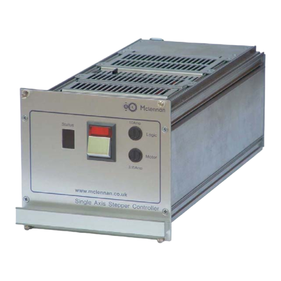
- Page 1 Mclennan Servo Supplies Ltd. User Manual SimStep Single Axis Stepper Drive & Controller...
- Page 2 User Manual for SimStep Single Axis Stepper Motor Drive and Controller Mclennan Drg. No. 3400 Issue D Associated Documents: MSE570 E2 Data Sheet PM600 Manual Software: McTerminal Terminal and Monitor Program The associated documents are available from the technical documents section of our web site www.mclennan.co.uk...
-
Page 3: Table Of Contents
NCODERS 11.3 C ............................30 ABLES 11.4 J ........................30 UNCTION OXES 11.5 J & J ......................30 OXES OYSTICK 11.6 EMC F ........................... 30 ERRITES ..........................31 IMITATIONS OF SimStep Manual - 3400 Iss. D June 2004 page 2... -
Page 4: Description
MSB867 Backplane MSE779 Power Supply Board These are mounted in a 3U high 28HP rack unit. The SimStep is supplied with a mains lead, an RS232 cable and an RS232 terminator. A range of standard motor, encoder, limits/datum and I/O cables are available. -
Page 5: Rear View
The power supply provides +24V (nominal) to energise the supply rail on the PM600 controller, and +40V (nominal) to energise the supply rail on the MSE570 drive. The PM600 manual referred to in this document can be found on www.mclennan.co.uk. 1.1 Rear View: Fig.1.2... - Page 6 This allows both replies from, and commands sent to, the controller to be echoed back. WARNING! To avoid overheating, the vents in the top and bottom of the unit must be unobstructed at all times. SimStep Manual - 3400 Iss. D June 2004 page 5...
-
Page 7: Link Settings
1.2 Link Settings The control operation of the SimStep can be configured by means of links fitted to the MSE867. The links can be accessed by removing the rear top cover of the unit. LK7 to LK1 Fig. 1 Link Location... -
Page 8: External Interface Connections
Link pins 4 and 11 to enable negative moves Link pins 5 and 12 for fast datum search If external ‘Abort Stop’ selected, link pins 7 and 14 to enable moves. SimStep Manual - 3400 Iss. D June 2004 page 7... - Page 9 Read Port 5 Read Port 6 Read Port 7 Read Port 8 Read Port Common (Isolated 0V) 0V (Controller 0V) Refer to PM600 Manual sections 2.18 and 3.16 for typical connections. SimStep Manual - 3400 Iss. D June 2004 page 8...
- Page 10 Connector type: 9 way 'D' type plug Terminal RS232 Connection RS485 Connection RS485-A Receive Data Link to echo replies and commands Transmit Data RS485-B Link to echo replies and commands SimStep Manual - 3400 Iss. D June 2004 page 9...
-
Page 11: Cables
3.1 Motor and Limit/Datum cables Motor and limit/datum cables fitted with connectors to plug into the rear panel of the SimStep may be specified. The available lengths are shown below. The motor cables have a connector on both ends, which can be connected either to the connector fitted to the stepper motor or to the stepper motor wires via an MSA889 Junction Box. -
Page 12: Encoder Cables
3.3 Encoder Cables SimStep can be connected to the encoder via an encoder cable that is equipped with connectors at each end. One connector plugs into the controller, the other into the motor- encoder extension cable as shown in fig 3.2. -
Page 13: Motor Connections
√2. The maximum drive current for coils wired in series is the unipolar motor phase current rating / √2. To reverse motor direction, swap the connections to one phase. E.g., swap B with B’. SimStep Manual - 3400 Iss. D June 2004... -
Page 14: Connecting To The Msa889 Junction Box
Motor Lead connections 126 mm 8 Lead motors 1’ 1’ Motor Lead 2’ 2’ 507MOCxx892 Motor Leads 3’ 3’ 4’ 4’ Junction Box MSA889 Fig. 4.5 Series Motor Coil Connections SimStep Manual - 3400 Iss. D June 2004 page 13... -
Page 15: Connection Of Limits And Datum
They should also be mounted for sliding operation, so that they do not become crushed on first use. No mechanism can decelerate instantaneously. SimStep Manual - 3400 Iss. D June 2004... -
Page 16: Datum Position
+VLL controller is configured to utilise the high-speed Lower Limit +VLL datum approach facility. Datum Approach +VLL Datum Stop +VLL Abort stop Fig. 4.6 Limit/Datum Connections SimStep Manual - 3400 Iss. D June 2004 page 15... -
Page 17: Power Supply Unit
3.15A for the motor rail and 1A for the logic rail. The mains voltage may be changed from 230V to 115V by changing the position of the links on the MSE779 PCB. SEL1 Fig. 5.1 Mains Voltage Selector SimStep Manual - 3400 Iss. D June 2004 page 16... -
Page 18: Mse570 Stepper Drive
Disable on Overtemperature - on Latch Overtemperature - on Current Control Type - slow Slave Sync – off 6.2 Current Setting As delivered the motor phase current is set to 3.5A/phase. SimStep Manual - 3400 Iss. D June 2004 page 17... -
Page 19: Other Mse570 Current Settings
34HSX-108 34HSX-208 0.0A 0.5A 0.9A 1.2A 1.3A 1.6A 1.85A 2.1A 2.3A 2.5A 2.7A 2.9A 3.0A 3.1A 3.3A 3.5A WARNING! Failure to make the correct current settings can damage the motor SimStep Manual - 3400 Iss. D June 2004 page 18... -
Page 20: Manual Operation Using The Jog Box Or Joystick
SF command into the SimStep during commissioning. Figures 7.1 to 7.3 show the connections of the JC series Jog Boxes to the SimStep. For single axis drives specify JC100 Jog box and connect it to the green ‘D’ connector on SimStep as shown in fig 7.1. -
Page 21: Single And Dual Axis Jog Box Operation
For 3-15 axes drives specify JC809 Jog Box and connect it to the green ‘D’ connector on SimStep as shown in fig. 7.3. JC809 Fit terminator Supplied with Use jog link cables 507JDC05916 JC809 Fig. 7.3 3-15 axis installations 7.2 Single and Dual Axis Jog Box Operation Jog box operation is very straightforward. -
Page 22: Joystick - Jc Series
Note that the SimStep is set up for Jog Box operation as standard. The controller must then be told to accept the joystick input using the command 1JM01000000 (see PM600 manual page 7-27). -
Page 23: Pm600 Intelligent Stepper Motor Controller
PM600 manual included with this documentation. The SimStep will operate under manual control with either a jog box or joystick, or can run under remote control through the RS232 (or RS485) interface. -
Page 24: Encoder Scaling
Any suitable communication programme can be used to communicate with the SimStep controller. For example, the MyTerminal programme (available from www.SimStep.co.uk) or the Windows Hyper Terminal programme can be used to make the communications link. Whichever software is used, the communications interface is set by default, as follows: Baud Rate... - Page 25 1 2 3 4 5 6 7 8 ULOAD LD2 LD3 SWAP8 Fig. 8.2 PM600 Switch Positions Fig. 8.3 Positions of PM600 Switches SW1, SW2 and SW3 SimStep Manual - 3400 Iss. D June 2004 page 24...
-
Page 26: General Command Structure
2MA-2000 Move Axis 2 to absolute position –2000 steps Output the encoder position of Axis 2 SimStep controller responds to all commands once the command has been accepted. However, not all commands can be accepted immediately. For example, a move command sent whilst a previous command is still taking place, will be delayed until the previous one is finished. -
Page 27: O Cable And Breakout Box
An I/O cable with the ‘breakout’ DIN rail mounting terminal box can be used to interface to SimStep without needing to make a special cable. The I/O breakout box features screw terminals to enable the 16 Digital I/O to be connected. -
Page 28: Isolation
This supply can either be a separate external supply or the SimStep’s internal +24V supply. If the internal supply is used, then the WP-com terminal must be connected the +VLL terminal on the Breakout box and the RP-com terminal must be connected the 0V terminal on the Breakout box. -
Page 29: Write Ports
9.4 Write Ports The write ports can be connected to an indicator (LED), an opto-isolator, a low-current relay or another SimStep’s read port. The WP(bit pattern) command is used to write to the output port. The bit pattern is specified as an eight digit binary number. The digits will be either characters 0, 1 or 2 starting with write port 8 through to 1. -
Page 30: Configuration
Save settings 10.3 Run Sequence Either the sequence can be run by sending a 1xs command or as sequence 0 has been set as an automatically executing sequence, by cycling the power to the SimStep. SimStep Manual - 3400 Iss. D... -
Page 31: Order Codes
11 Order Codes 11.1 System Type Order Code SimStep 508SMS09749 11.2 Motor Encoders Frame size Type Order Code Size 23 23HSX-206 CI 500L 301HSE00053 23HSX-306 CI 500L 301HSE00054 Size 34 34HSX-108 RI 500L 301HSE00055 34HSX-208 RI 500L 301HSE00056 11.3 Cables... -
Page 32: Limitations Of Use
Incorrect operation can also lead to damage to the motor or associated machinery. SimStep Manual - 3400 Iss. D June 2004...
Need help?
Do you have a question about the SimStep and is the answer not in the manual?
Questions and answers