Shinko JIR-301-M Instruction Manual
Digital indicator
Hide thumbs
Also See for JIR-301-M:
- Communication instruction manual (36 pages) ,
- Instruction manual (16 pages) ,
- Instruction manual (4 pages)
Table of Contents
Advertisement
Quick Links
Advertisement
Table of Contents

Related Manuals for Shinko JIR-301-M

Summary of Contents for Shinko JIR-301-M
- Page 1 DIGITAL INDICATOR JIR-301-M Instruction Manual...
- Page 2 • Any unauthorized transfer or copying of this document, in part or in whole, is prohibited. • Shinko Technos Co., Ltd. is not liable for any damage or secondary damage(s) incurred as a result of using this product, including any indirect damage.
- Page 3 Caution This instrument is intended to be used under the following environmental conditions (IEC61010-1): Overvoltage category , Pollution degree 2 Ensure the mounting location corresponds to the following conditions: • A minimum of dust, and an absence of corrosive gases •...
- Page 4 Characters used in this manual ( : No character is indicated.) Indication Number, Indication Alphabet Indication Alphabet...
-
Page 5: Table Of Contents
Contents 1. Model..............................1.1 Model ............................1.2 How to Read the Model Label ..................... 2. Name and Functions ........................3. Mounting to the Control Panel ......................3.1 Site Selection ..........................3.2 External Dimensions (Scale: mm)....................3.3 Panel Cutout..........................3.4 Mounting the Unit ........................4. -
Page 6: Model
1. Model 1.1 Model JIR-301-M □, □□□ Series name: JIR-301-M (W96 x H48 x D100 mm) Input Multi-range (*1) Power supply 24 V AC/DC (*2) Alarm 4 output (*3) Serial communication (RS-485)(*4) Insulated power output 24 3 V DC (*5) Insulated power output 5 0.5 V DC (*5) -
Page 7: How To Read The Model Label
Example Terminal arrangement Terminal arrangement of JIR-301-M ① C5, TA(0 to 20), TA2(0 to 20) Model JIR-301-M C5, TA(0 to 20), TA2(0 to 20) ② Input MULTI-RANGE (Multi-range input) ③ A1, A2, A3, A4, P24, P5 outputs A1, A3: 3 A 250 V AC ④... -
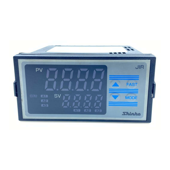
Page 8: Name And Functions
2. Name and Functions FAST key UP key PV Display SV Display HOLD indicator TX/RX indicator A1 to A4 value indicator A1 to A4 action indicator DOWN key MODE key (Fig. 2-1) Display, Indicator Name Description PV Display Indicates PV (process variable) or characters in the setting mode with the red LED. SV Display Indicates A1/A2/A3/A4 value or the set value in the setting mode with the green LED. -
Page 9: Mounting To The Control Panel
3. Mounting to the Control Panel 3.1 Site Selection This instrument is intended to be used under the following environmental conditions (IEC61010-1): Overvoltage category , Pollution degree 2 Ensure the mounting location corresponds to the following conditions: • A minimum of dust, and an absence of corrosive gases •... -
Page 10: Mounting The Unit
(Fig. 3.4-1) Caution As the case of the JIR-301-M is made of resin, do not use excessive force while tightening screws, or the mounting brackets or case could be damaged. 0.12 N•m of torque is recommended. -
Page 11: Wiring
4. Wiring Warning Turn the power supply to the instrument off before wiring or checking. Working on or touching the terminal with the power switched on may result in severe injury or death due to electrical shock. Caution • Do not leave wire remnants in the instrument, as they could cause a fire or malfunction. •... -
Page 12: Lead Wire Solderless Terminal
Terminal Name Description Ground terminal Power supply TRANSMIT OUTPUT1 Transmission output 1 A1 output A2 output A3 output EVENT INPUT Event input Thermocouple input RTD input Direct current input, DC voltage input For Direct current input (externally mounted 50 shunt resistor), connect a 50 shunt resistor (sold separately) between input terminals. -
Page 13: Setup
5. Setup After power is turned ON, the input characters and temperature unit will be indicated on the PV Display, and the input range high limit (for thermocouple, RTD input) or scaling high limit (for Direct current, DC voltage input) will be indicated on the SV Display for approx. 3 sec. (Table 5-1) During this time, all outputs and LED indicators are in an OFF status. -
Page 14: Alarm Setting Mode
5.2 Alarm Setting Mode If the MODE key is pressed in PV/SV display mode, the unit will move to Alarm setting mode. Character Setting Item, Function, Setting Range Factory Default A1 value • Sets A1 output action point. • Not available if No alarm action is selected in [A1 type] •... -
Page 15: Auxiliary Function Setting Mode 1
Available only when Serial communication (C5 option) is ordered. • : Shinko protocol : Modbus ASCII mode : Modbus RTU mode : Shinko protocol (Block read available) : Modbus ASCII mode (Block read available) : Modbus RTU mode (Block read available) - Page 16 Character Setting Item, Function, Setting Range Factory Default Instrument number • Sets the individual instrument number of this unit. (The instrument numbers should be set one by one when multiple instruments are connected in Serial communication.) • Available only when the Serial communication (C5 option) is ordered •...
- Page 17 Input Value Correction Input value can be corrected in [Sensor correction coefficient] and [Sensor correction] in Auxiliary Function Setting Mode 1. In [Sensor correction coefficient], set the slope of temperature change. In [Sensor correction], set the difference between temperatures before correction and after correction. PV after input correction is expressed by the following formula.
-
Page 18: Auxiliary Function Setting Mode 2
5.4 Auxiliary Function Setting Mode 2 To enter Auxiliary Function Setting Mode 2, press and hold the UP, DOWN and MODE keys (in that order) together for approx. 3 seconds in PV/SV Display Mode. Character Setting Item, Function, Setting Range Factory Default Input type •... - Page 19 Character Setting Item, Function, Setting Range Factory Default Decimal point place • Selects decimal point place. • Available when direct current or DC voltage input is selected in [Input type]. • : No decimal point : 1 digit after decimal point : 2 digits after decimal point : 3 digits after decimal point PV filter time constant...
- Page 20 Character Setting Item, Function, Setting Range Factory Default A4 type • Selects an A4 type. See Section 7.1 (p.27). Available when Alarm 4 output (A4 option) is ordered. • If A4 type is changed, A4 value will default to 0 (0.0). •...
- Page 21 Character Setting Item, Function, Setting Range Factory Default A4 Energized/De-energized • Selects A4 Energized/De-energized. Available only when Alarm 4 output (A4 option) is ordered. Not available if No alarm action is selected in [A4 type]. • : Energized : De-energized A1 hysteresis •...
- Page 22 Character Setting Item, Function, Setting Range Factory Default A3 delay time • Sets A3 action delay time. When setting time has elapsed after the input enters the alarm output range, the alarm is activated. • Not available if No alarm action or High/Low limit range alarm is selected in [A3 type].
- Page 23 Character Setting Item, Function, Setting Range Factory Default Transmission output 2 low limit • Sets the Transmission output 2 low limit value. Available when Transmission output 2 (T□2 option) is ordered. 4-20 mA DC Equals 4 mA DC output. 0-20 mA DC Equals 0 mA DC output.
- Page 24 Character Setting Item, Function, Setting Range Factory Default A2 HOLD function • Enables/Disables the A2 HOLD function. Not available if No alarm action is selected in [A2 type]. Not available if Insulated power output (P24 option or P5 option) is ordered. •...
-
Page 25: Maintenance Mode
5.5 Maintenance Mode To enter Maintenance mode, press the UP and FAST keys (in that order) together for approx. 5 seconds in PV/SV Display Mode. If the unit enters Maintenance mode, all outputs are forced to turn OFF. Character Setting Item, Function, Setting Range Factory Default A1 output ON/OFF •... -
Page 26: Operation
6. Operation 6.1 Operation After the JIR-301-M is mounted to the control panel and wiring is completed, operate the unit following the procedure below. (1) Turn the power supply to the JIR-301-M ON. For approximate 3 sec after the power is switched ON, the input characters and the temperature unit are indicated on the PV Display, and input range high limit (thermocouple, RTD input) or scaling high limit (Direct current, DC voltage input) is indicated on the SV Display. -
Page 27: Alarm Action
7. Alarm Action 7.1 High Limit Alarm, Low Limit Alarm : A1 output terminals (7, 8) ON : A1 output terminals (7, 8) ON or OFF : A1 output terminals (7, 8) OFF : A1 output is in standby. • The following terminal numbers are used for respective alarm outputs. A2 output terminals: 9, 10 A3 output terminals: 12, 13 A4 output terminals: 15, 16... -
Page 28: A3 High/Low Limit Range Alarm Action
7.2 A3 High/Low Limit Range Alarm Action : A1 output terminals (7, 8): OFF, A2 output terminals (9, 10): OFF, A3 output terminals (12, 13): ON : A1 output terminals (7, 8), A2 output terminals (9, 10) and A3 output terminals (12, 13): ON or OFF : A1 output terminals (7, 8): ON, A2 output terminals (9, 10): ON, A3 output terminals (12, 13): OFF... -
Page 29: Specifications
Allowable input voltage: 15 V DC max. Allowable signal source resistance: 100 max. Power supply Model JIR-301-M JIR-301-M 1 voltage Power supply voltage 100 to 240 V AC 50/60Hz 24 V AC/DC 50/60Hz Allowable voltage 85 to 264 V AC... - Page 30 Standard Function The alarm action point can be set at random (process alarm), and if the input A1 output, reaches the randomly set action point, the alarm output turns ON or OFF A2 output, corresponding to the alarm type and Energized/De-energized selection. A3 output The alarm type can be selected from;...
- Page 31 Input terminal and ground terminal: 1.5 kV AC for 1 minute Dielectric Input terminal and power terminal: 1.5 kV AC for 1 minute strength Power terminal and ground terminal: 1.5 kV AC for 1 minute Output terminal and ground terminal: 1.5 kV AC for 1 minute Output terminal and power terminal: 1.5 kV AC for 1 minute Output terminals: A1, A2, A3 and A4 output terminals, Transmission output 1 terminals, Transmission output 2 terminals and communication terminals...
- Page 32 The CPU is monitored by a watchdog timer, and if an abnormal status is found on Self-diagnosis the CPU, the JIR-301-M is switched to warm-up status. Automatic cold This detects the temperature at the connecting terminal between the thermocouple and junction temp.
-
Page 33: Optional Specifications
Synchronization method Parity Even, Odd , No parity (Selectable by keypad) Stop bit 1, 2 (Selectable by keypad) Communication Shinko protocol, Modbus ASCII, Modbus RTU protocol In addition, each protocol above is available with Block read. (Selectable by keypad) Connectable number... - Page 34 If this option is ordered, the A2 function will be disabled. Insulated power This option cannot be used with the Insulated power output (P5 option) together, output or cannot be used with Power for 2-wire transmitter (DSB option) together. (P24 option) Output voltage 24 3 V DC (When load current is 30 mA) Ripple voltage...
-
Page 35: Troubleshooting
9. Troubleshooting If any malfunctions occur, refer to the following items after checking that power is being supplied to the JIR-301-M. Problem Possible Cause Solution Internal memory is defective. Contact us or our agency in your region. The PV Display... - Page 36 Problem Possible Cause Solution The PV Display Check whether the input signal How to check whether the input signal wire is keeps indicating wires of DC voltage (0 to 5 V disconnected the value set in DC, 0 to 10 V DC) and direct [DC voltage (0 to 5 V DC, 0 to 10 V DC)] [Scaling low limit].
-
Page 37: Character Table
10. Character Table Depending on the model and setting contents, some setting items do not appear. 10.1 Alarm Setting Mode If the MODE key is pressed in PV/SV Display Mode, the unit will move to Alarm setting mode. Character Setting Item, Function, Setting Range Factory Default A1 value •... -
Page 38: Auxiliary Function Setting Mode 1
• : Shinko protocol : Modbus ASCII mode : Modbus RTU mode : Shinko protocol (Block read available) : Modbus ASCII mode (Block read available) : Modbus RTU mode (Block read available) Instrument number • Setting range: 0 to 95 Communication speed •... -
Page 39: Auxiliary Function Setting Mode 2
10.3 Auxiliary Function Setting Mode 2 To enter Auxiliary Function Setting Mode 2, press and hold the UP, DOWN and MODE keys (in that order) together for approx. 3 seconds in PV/SV Display Mode. Character Setting Item, Function, Setting Range Factory Default Input type (Table 10.3-1) - Page 40 Characters, Setting Item, Function, Setting Range Factory Default A2 type • : No alarm action : High limit alarm : Low limit alarm : High limit with standby alarm : Low limit with standby alarm A3 type • : No alarm action : High limit alarm : Low limit alarm : High limit with standby alarm...
- Page 41 Characters, Setting Item, Function, Setting Range Factory Default A1 delay time • Setting range: 0 to 9999 seconds A2 delay time • Setting range: 0 to 9999 seconds A3 delay time • Setting range: 0 to 9999 seconds A4 delay time •...
-
Page 42: Maintenance Mode
Characters, Setting Item, Function, Setting Range Factory Default A2 HOLD function • : Disabled : Enabled A3 HOLD function • : Disabled : Enabled A4 HOLD function • : Disabled : Enabled Square root function • : Disabled : Enabled Low level cutoff •... - Page 44 Please provide your model and serial number. (e.g.) • Model ---------------- JIR-301-M • Serial number ----- No. 165F05000 In addition to the above, please let us know the details of the malfunction, or discrepancy, and the operating conditions.
Need help?
Do you have a question about the JIR-301-M and is the answer not in the manual?
Questions and answers