Advertisement
Quick Links
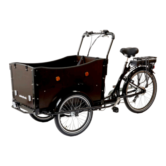
ELECTRICAL CARGO BIKE
SAMLEMANUAL
ASSEMBLE MANUAL
Read and understand these instructions before you begin the assembly. The bike comes
partly assembled, and it is important to read the manual carefully before starting
assembly, so the bicycle will be assembled in the correct order. It is recommended to be
two people to assemble the cargo bike. Be aware that the bike must be re-tightened after
approx. 20 km. Make sure to check all parts of the bike and re-tighten all moving parts,
including breaks, spokes, bolts and nuts.
with mechanical disc breaks
Page 1
Advertisement

Related Manuals for AMLAD CYKLER Electrical Cargo Bike


Summary of Contents for AMLAD CYKLER Electrical Cargo Bike
- Page 1 ELECTRICAL CARGO BIKE with mechanical disc breaks SAMLEMANUAL ASSEMBLE MANUAL Read and understand these instructions before you begin the assembly. The bike comes partly assembled, and it is important to read the manual carefully before starting assembly, so the bicycle will be assembled in the correct order. It is recommended to be two people to assemble the cargo bike. Be aware that the bike must be re-tightened after approx. 20 km. Make sure to check all parts of the bike and re-tighten all moving parts, including breaks, spokes, bolts and nuts. Page 1...
- Page 2 Step 1: Assembly of the back and front frame • When the parts have been taken out of the boxes and wrapping, place the front frame upside down on two chairs (see picture 1A). • Place the back frame upside down "on top” of the front frame. Avoid taking the plastic on the luggage carrier off to avoid scratches in the paint. • The main bolt is mounted from below as shown in picture 1B by using a hammer or something similar. It should fit tightly. The bearings should be lubricated with grease. Do not tighten the nut yet. Billede 1B Picture 1A • With the 7 large bolts, washers and nuts mount the bow-shaped and the two straight metal rods as shown on image 1C, 1D and 1E. The metal rods must be placed below the trazezodial plate and on top of the frame as shown in the pictures. In order to avoid that the stainless steel locknuts get stuck halfway down on the bolt, use some grease at the end of the bolts, before the nut is tightened. Only when these are tightened, tighten the large nut on the main bolt as hard as possible, and insert the split. • 7 pc. 13 mm bolts (length: 25 mm) • 7 pc. washers • 7 pc. 13 mm nuts Picture 1C Page 2...
- Page 3 Picture 1D Picture 1E Picture 1F Step 2: Fenders, front wheels and brake pads • One of the chairs is moved to the end of the front frame and the second chair is removed. • The front fenders are mounted with 8 small bolts, washers, and nuts + the four brackets (see picture 2A and 2B). To make sure that the fenders are just above the wheels, the nuts are tightened after the wheels are mounted. • 8 pc. 8 mm bolts (length: 12 mm) • 8 pc. washers • 8 pc. 8 mm nuts Page 3...
- Page 4 Picture 2A Picture 2B • The two break calibers are mounted with the 2x2 black umbraco bolts. Notice: use 2-3 ekstra washers per umbraco bolt to ensure a good distance from the end of the bolt to the break disc. Se picture 2D and 2E. • 2 break calibers • 2x2 black umbraco bolts with 2-3 ekstra washers Picture 2C Picture 2D Picture 2E Page 4...
- Page 5 • The break discs are mounted on the front wheels with the 2 x 6 small black torx bolts – see picture 2F. • Mount the front wheels as in picture 2G. • The position of the break calibers versus the break discs are adjusted via the blank umbraco-disc on the outside og the kaliber and the side-by-side adjustment bolts on the break caliber – see picture 2H and 2I. The break discs should in this way run freely without touching the break pads when the wheel is turned. It is however OK if there is a small ”whisling” sound from the break when the wheel is turned – this will disappear after a few days of use. • Then the bike is turned (see picture 2J). • 2 pc. break discs • 2 x 6 small black torx bolts Picture 2F Picture 2G Picture 2H Picture 2I Picture 2J Page 5...
- Page 6 Step 3: Assemble the box • The corner brackets for the box are mounted as shown in picture 3A – with the nuts on the inside. • The correct position of the four different corner fittings is shown on picture 3B. • 8 pc. 10 mm bolts (length 30 mm) • 8 pc. washers • 8 pc. 10 mm lock nuts Picture 3B Picture 3A The following is mounted loosely and tightened in the end: • The front and back panels are mounted (see picture 3C) with 12 og the 10 mm bolts, washers and rounded nuts as illustrated below – with the nuts on the outside. • The side panels are mounted (see picture 3D) with the remaining 8 of the 10 mm bolts, washers and rounded nuts. The four canopy holders are mounted with the long bolts in the holes in the middle (see picture 3E below). All nuts on the outside. • The base panel is mounted (see picture 3F) – with the nuts on the underside. • And then all bolts and nuts are tightened. • 20 pc. 10 mm bolts • 4 pc. 10 mm boltt (length 30 mm) • 4 plastic elements for canopy-mounting (length 18 mm) • 20 pc. washers • 4 pc. washers • 4 pc. 10 mm rounded nuts • 20 pc. 10 mm rounded nuts Page 6...
- Page 7 Picture 3D Picture 3E Picture 3C • 2 pc. 10 mm bolts (length 70 mm) • 2 pc. washers • 2 pc. 10 mm lock nuts Picture 3F • The two step boards and reflectors are mounted (see picture 3G, 3H and 3I). • 2 pc. step boards • 4 pc. yellow side-reflectors • 4 pc. 10 mm bolts • 2 pc. white front-reflectors (length 18 mm) • 4 pc. washers • 4 pc. 10 mm rounded nuts Page 7...
- Page 8 Picture 3G Picture 3I Picture 3H Step 4: The rest of the equipment • The head light is mounted (see picture 4A) with the last small 8 mm bolt (same type as for the front fenders). Picture 4A • The pedals are mounted (see picture 4B) – note that they have left-thread and that the pedals have left / right markings. Picture 4B Page 8...
- Page 9 • The child seats are mounted with four screws (see picture 4C). The seat belts are mounted on the outside of the box (front- and back panel) and below the child seats (see picture 4C and 4D). • 8 pc. 10 mm bolts Picture 4C Picture 4D (length 18 mm) • 8 pc. washers • 8 pc. 10 mm lock nuts • The plastic fittings for the steer and the canopy-holders are mounted with a small hammer (see picture 4E and 4F). • The plastic-fittings for the wheel nuts are mounted with a small hammer (ses picture 4G). Picture 4G Picture 4F Picture 4E Page 9...
- Page 10 • The saddle is mounted on the saddle post and this is mounted on the bike (see picture 4H) Picture 4H • The handlebar is mounted and the break handles, gear shifter, display and bell are mounted on the handlebar (see picture 4I, 4J, 4K, 4L). Picture 4I Picture 4J Picture 4K Picture 4L Page 10...
- Page 11 Step 5: Brake cables and adjustment of breaks and gear • The back-break is mounted (ses picture 5A and 5B): • The umbraco bolt on the break arm is loosened • Make sure that the break pads are in the right position versus the rim on both sides • The screws on each side of the break arms are adjusted so that the two arms are equally tight when pushed against the rim • Give a couple of mm space to the rim on each side before the umbraco bolt is tightened. Picture 5A Picture 5B • The front cables are mounted in the break handle (see picture 5C). They are pulled through the hole in the handle bar (see picture 5D) and through the cable holders (see picture 5E and 5F). The cables are mounted on the break calibers so that the break discs can move freely. It is however OK if there is a small ”whisling” sound from the break when the wheel is turned – this will disappear after a few days of use. • Final adjustment is done partly at the break calibers (see picture 2H and 2I) and partly via the two small blank screws at the break handle (see picture 5C) – until the bike breaks even and effectively. Picture 5C Picture 5D Picture 5E Picture 5F Picture 5G Page 11...
- Page 12 • The gear is tested. If the gear ”clicks” or you experience difficulties in changing gear, you can adjust the gear by using the small black ”hand-screw” where the gear cable is mounted on the gear shift )see picture 5F). Billede 5F IMPORTANT: • The frame number is stamped into the frame on the left side of the bike – just in front of the left pedal. • Remember to adjust and re-tighten all moving parts on the bike after some weeks of use. If re- tightening of the spokes are needed, please use a spoke tightener. • See our ”Let us help” guides on www.amladcykler.dk. ENJOY YOUR NEW CARGO BIKE…! Page 12...
Need help?
Do you have a question about the Electrical Cargo Bike and is the answer not in the manual?
Questions and answers