Table of Contents
Advertisement
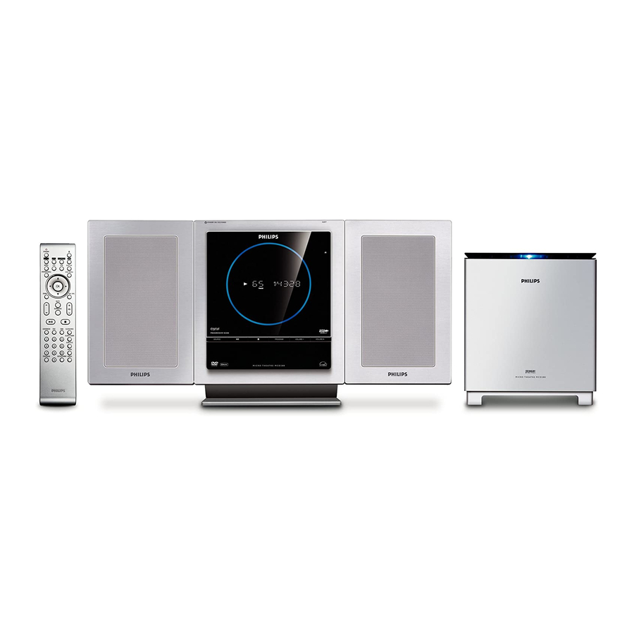
DVD Micro Theatre
©
Copyright 2009 Philips Consumer Electronics B.V. Eindhoven, The Netherlands
All rights reserved. No part of this publication may be reproduced, stored in a retrieval system or
transmitted, in any form or by any means, electronic, mechanical, photocopying, or otherwise without
the prior permission of Philips.
Published by SL 0910 Service Audio
Version 1.6
TABLE OF CONTENTS
Technical Specifi cations .............................................. 1-2
Measurement setup ..................................................... 1-3
Service Aids, Safety Instruction, etc. .................1-4 to 1-5
Lead-free Information & Service Instruction ......1-6 to 1-7
Installation & Preparations & Controls ............1-8 to 1-15
Troubleshooting .............................................1-15 to 1-16
Disassembly Instructions & Service positions ................ 2
Service Test Programs ................................................... 3
Set Block Diagram .......................................................... 4
Set Wiring diagram ......................................................... 5
Display Board & AMP Key Board ................................... 6
Tuner Board .................................................................... 7
Power Board .................................................................. 8
Woofer Output Board ...................................................... 9
Scart Board................................................................... 10
Set Mechanical Exploded View & Parts List ................. 11
Electrical Parts List ....................................................... 12
Revision List ................................................................. 13
Printed in The Netherlands
P
a
g
e
Subject to modifi cation
MCD288
/All Versions
VIDEO CD
CLASS 1
LASER PRODUCT
GB
3141 785 30806
Advertisement
Table of Contents
Troubleshooting

Related Manuals for Philips MCD288/12


Summary of Contents for Philips MCD288/12
- Page 1 LASER PRODUCT © Copyright 2009 Philips Consumer Electronics B.V. Eindhoven, The Netherlands All rights reserved. No part of this publication may be reproduced, stored in a retrieval system or transmitted, in any form or by any means, electronic, mechanical, photocopying, or otherwise without the prior permission of Philips.
- Page 2 LOCATION OF PCBS VERSION VARIATIONS: Type /Versions: MCD288 Features & Board in used: Aux in / CDR in Line Out Video Out Surround Out Subwoofer Out Power Booster Out S-Video Out Scart Out Matrix Surround News Dolby Pro Logic (DPL) Incredible Surround Karaoke Features Voltage Selector...
- Page 3 SPECIFICATION GENERAL: COMPACT DISC: Mains voltage : 230V ± 10% /12 , 220V ± 10% /93 Measurement done at output conn. of the DVD module. 120V ± 10% / 230V ± 10% /55/96/98 Frequency response within ± 1.0dB : 20Hz - 20kHz 120V ±...
- Page 4 To avoid wear-out of tips switch off un-used equipment, or reduce heat. • Mix of lead-free solder alloy / parts with leaded solder alloy / parts is possible but PHILIPS recommends strongly to avoid mixed solder alloy types (leaded and lead-free).
- Page 5 INSTALLATION...
- Page 6 INSTALLATION...
- Page 7 1-10 INSTALLATION...
- Page 8 1-11 INSTALLATION...
- Page 9 1-12 PREPARATIONS...
- Page 10 1-13 PREPARATIONS...
- Page 11 1-14 CONTROLS...
- Page 12 1-15 CONTROLS & TROUBLESHOOTING...
- Page 13 1-16 TROUBLESHOOTING...
- Page 14 DISMANTLING INSTRUCTIONS Dismantling of the Front Panel assembly Dismantling of the PCB assemblies and modules 1) Loosen & remove 4 screws A (see figure 1). 1) Loosen 4 screws B to remove DVD Loader as shown in 2) Place a small flat screw driver in between the front & rear Figure 3.
- Page 15 Dismantling of the PCB assemblies and modules Dismantling of the Subwoofer 5) Loosen 3 screws I to remove the Power Board mounting 4) Loosen 10 screws L to remove subwoofer bottom cover as shown in Figure 7. it to the Rear Cabinet as shown in Figure 5. 6) Loosen 2 nuts from D-SUB jack on the rear side of the Rear Cabinet to separate it from the Rear panel.
- Page 16 Service pos B Note: After re-assembly, it is very important to ensure all wires are routed properly to ensure that they do not touch/obstruct all moving parts. Service pos C...
-
Page 17: Service Test Programs
SERVICE TEST PROGRAM To start service test program To check MPEG software hold 38 & 7 button on version hold the System the set depressed while Menu button on Remote plugging in the mains cord Control Select SYSTEM SETUP Display shows the on TV display MCU version "MCD288 VXX"... -
Page 18: Set Block Diagram
SET BLOCK DIAGRAM... - Page 19 SET BLOCK DIAGRAM...
-
Page 20: Display Board & Amp Key Board
LAYOUT DIAGRAM - AMP KEY BOARD DISPLAY & AMP KEY BOARD For Version 37, the board is not intented to be repaired on component level. Circuit Diagram and Printed Circuit Board drawings are published for orientation only. In case of defects please replace the entire board. The Display Board and AMP Key Board can be ordered with codenumber "9940 000 04868"... - Page 21 LAYOUT DIAGRAM - DISPLAY BOARD TOP VIEW...
- Page 22 LAYOUT DIAGRAM - DISPLAY BOARD BOTTOM VIEW...
- Page 23 CIRCUIT DIAGRAM - DISPLAY & KEY BOARD CN305 CN306 CN302 22P/1.25 14P/1.25 VFD301 S301 MCD288VFD C344 REMOTE 10uf/50v 10uf/50v 10uf/50v R323 C313 C301 C345 10uf/50v R322 R305 C315 .47/0.5 47uf/16v C314 SW309 IC301 SW305 SW310 7805 OP/CL STANDBY VOLUME- DZ301 R324 D302 R320...
-
Page 24: Tuner Board
PCB LAYOUT - TOP VIEW TUNER BOARD The board is not intented to be repaired on component level. Circuit Diagram and Printed Circuit Board drawings are published for orientation only. In case of defects please replace the entire board. The board can be ordered with codenumber "9940 000 04875". - Page 25 CIRCUIT DIAGRAM +5V0 27pF 100p 120nH 22uf/10v 2.2K 472p 2.2K 100K 223p 104p +5V0 220uf/10v 5.1V 1uf/50v 104p 393p 33nH 2.2K LDE2 100K VCO1 LDE1 2.2K VCD2 TIFC VCCosc VREF TEA5768HL 104p DGND MPXO NECTAR-C VCCD TMUT 103p 1uf/50v DATA VAFL 223p CLOCK...
-
Page 26: Power Board
POWER BOARD For Version 37, the board is not intented to be repaired on component level. Circuit Diagram and Printed Circuit Board drawings are published for orientation only. In case of defects please replace the entire board. The Power Board can be ordered with codenumber "9940 000 04865" for /37. - Page 27 LAYOUT DIAGRAM - POWER BOARD...
- Page 28 CIRCUIT DIAGRAM - POWER BOARD CN211 CN210 CN212 CN205 6p/2.0 14p/1.25 7p/2.0 22p/1.25 R261 R260 Q204 CN207 8550 CN213 +12V-2 +12V R230 DGND 47/0.25W R213 R214 R248 R250 4.7K 4.7k 2p/2.5 R249 1.5K CN214 R/SC R225 16:9-VS RF2-1 Q205 100uf/16v CN215 RGB-SW R240...
-
Page 29: Woofer Output Board
LAYOUT DIAGRAM - WOOFER TERMINAL BOARD (9940 000 04873) WOOFER OUTPUT BOARD For Version 37, the board is not intented to be repaired on component level. Circuit Diagram and Printed Circuit Board drawings are published for orientation only. In case of defects please replace the entire board. LAYOUT DIAGRAM - WOOFER LAMP BOARD The Power Board can be ordered with codenumber "9940 000 04871"... - Page 30 LAYOUT DIAGRAM - WOOFER OUTPUT BOARD...
- Page 31 CIRCUIT DIAGRAM - WOOFER OUTPUT BOARD IC503 L502 TDA7264 R555 R554 C522 4.7/0.25 4.7uf/25v R556 IC504 C523 C524 TDA7264 104(M) C580 R547 R557 333(M) 562(M) R561 104(M) C526 R558 R559 OUT2 4.7/0.25 R548 R562 C581 L501 -Vcc -VCC OUT1 333(M) R544 CN507 R564...
- Page 32 ELECTRICAL PARTS LIST - WOOFER OUTPUT BOARD C506 9940 000 04971 NONINDUCTIVE CAP. 334J 100V C524 9940 000 04972 MYLAR CAP. 5600P 100V K-5 C560 9940 000 04973 ELEC. CAP. 4700µF 35V C561 9940 000 04973 ELEC. CAP. 4700µF 35V 9940 000 03502 THYRISTOR RS808 IC1301 9940 000 03767 IC TDA7265 STEREO POWER IC IC501...
-
Page 33: Scart Board
10-1 10-1 LAYOUT DIAGRAM - VIDEO OUTPUT BOARD SCART & VIDEO OUTPUT BOARD CIRCUIT DIAGRAM - VIDEO BOARD CN701 For Version 37 and Version12, the board is not intented to be repaired on component level. Circuit Diagram and Printed Circuit Board drawings are published for orientation only. - Page 34 11-1 11-1 SET MECHANICAL EXPLODED VIEW...
-
Page 35: Electrical Parts List
11-2 11-2 MECHANICAL & ACCESSORIES PARTS LIST ELECTRICAL PARTS LIST- MISCELLANEOUS 9940 000 04862 ECO POWER PCB ASS'Y /12/37 9940 000 04865 POWER PCB ASS'Y 9940 000 05011 PUSH-DOOR /93/98/55 9940 000 04881 WOOFER SPEAKER 8R 50W 9965 100 17680 DISPLAY PCB ASS'Y /98 9940 000 04912 ADDITIONAL-KEY-PANEL... -
Page 36: Display Board
12-1 ELECTRICAL PARTS LIST ELECTRICAL PARTS LIST - DISPLAY BOARD - POWER BOARD IC301 9940 000 04953 IC LM340T5 7805 C290 9940 000 04932 ELE. CAP. 3300µF 35V IC302 9940 000 04957 CPU 3S9228 CN201 9940 000 04943 S-SOCKET DS-106 IC303 9940 000 04953 IC LM340T5 7805... - Page 37 12-2 ELECTRICAL PARTS LIST ELECTRICAL PARTS LIST - WOOFER OUTPUT BOARD - SCART BOARD (ONLY FOR /12) C506 9940 000 04971 CAP. 334J 100V JCK801 9940 000 04983 RCA SOCKET AV-8.4-0.8B C524 9940 000 04972 MYLAR CAP. 5600P 100V JCK802 9940 000 03511 SCART 21P SOCKET C560 9940 000 04973 ELEC.
- Page 38 12-3 ELECTRICAL PARTS LIST - AMP KEY BOARD J104 9940 000 04966 HEADPHONE JACK D3.5 J105 9940 000 04967 AUX IN JACK CK3511 J106 9940 000 04968 USB JACK A-TYPE 4P LED101 9940 000 02537 LED (BLUE) LED102 9940 000 02537 LED (BLUE) SW101 9940 000 04965...
-
Page 39: Revision List
13 - 1 REVISION LIST 1.0 Manual 3141 785 30800 Initial Service Manual released. 1.1 Manual 3141 785 30801 In this version, the content of Chapter 9 and Chapter 11 are corrected and updated. Page 9-2: Layout Diagram-Woofer Output Board corrected. Page 9-3: Circuit Diagram-Woofer Output Board corrected.
Need help?
Do you have a question about the MCD288/12 and is the answer not in the manual?
Questions and answers