Table of Contents
Advertisement
Quick Links
Advertisement
Table of Contents

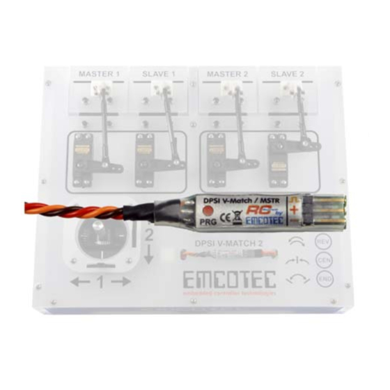
Summary of Contents for Emcotec DPSI V-Match
- Page 1 Bedienungsanleitung...
- Page 2 DPSI V-Match Operating Instructions Version 1.0 Page 2 of 16...
-
Page 3: Table Of Contents
DPSI V-Match Operating Instructions Version 1.0 Contents 1. Functionality..................4 2. Programming ................... 6 2.1. Changing Servo Direction............7 2.2. Calibrating Servo Center ............8 2.3. Calibrating End-Limits.............. 9 2.4. Deleting all Programming ............10 3. Additional Hints................11 3.1. Adapting several Servos............11 3.2. -
Page 4: Functionality
(i.e. flashes) until power is turned off. Powerful Servos: The electronically design of the DPSI V-Match allows for usage of powerful digital servos; supply voltage ranging up to 8.4 volts. Due to the PCB (4-layer) and the thick (0.34 mm ) connection cable, current load is especially high. - Page 5 Because of the intelligent software design and a highly accurate crystal oscillator, a resolution of more than 3000 steps is obtained. Therefore, the DPSI V-Match is also suitable for modern remote control systems with high servo positioning precision (number of steps).
-
Page 6: Programming
2. Programming There is no external programming device necessary, e.g. a PC or a programming box for programming of the DPSI V-Match. Only a delivered magnet serves for activation of the corresponding programming functions. Everything else is conducted with the transmitter and remote control equipment. -
Page 7: Changing Servo Direction
Version 1.0 Hint: Whenever programming takes place, the integrated red LED blinks for controlling purposes at a rate of 0.5Hz (1s on, 1s off) at the DPSI V-Match's side. 2.1. Changing Servo Direction When changing the direction of the servo, all... -
Page 8: Calibrating Servo Center
If the stick remains in one end-position, steps automatically increment or decrement after 2.5 seconds. This serves for quicker settings of the values. Hint: Due to the high resolution of the DPSI V-Match, changes of the servo position are possibly recognizable only after several steps. Page 8 of 16... -
Page 9: Calibrating End-Limits
Operating Instructions Version 1.0 Remove the magnet from its red dot position ("PRG") as soon as the slave servo reaches the desired center position. The DPSI V-Match now starts with the newly programmed center position of the slave servo. Hint: Reprogram the end-limits in order to obtain linear curves after programming the servo center. -
Page 10: Deleting All Programming
DPSI V-Match takes place. Now, the magnet can be removed. Hint: Whenever programming takes place, the integrated red LED blinks for controlling purposes at a rate of 0.5Hz (1s on, 1s off) at the DPSI V-Match's side. Page 10 of 16... -
Page 11: Additional Hints
DPSI V-Match connects to the MSTR output of the first DPSI V-Match. Now, a SLAVE output is available at the first DPSI V-Match, a MSTR and a SLAVE output at the second one. Both SLAVE servos can now be independently set up. -
Page 12: Changing The Model
Version 1.0 3.2. Changing the Model If a programmed DPSI V-Match is to be used in an other application (e.g. changing a model), generally all settings should be deleted (see also "Deleting all Programming"). This is also true if a servo with a different rotating direction is to be built in. - Page 13 DPSI V-Match Operating Instructions Version 1.0 The "distance" of the maximum position of a servo in respect to its center must be at least 20%, otherwise the value is not programmable. Range checking accompanies each programming. It is therefore not possible to position the servo center position off limits.
-
Page 14: Technical Data
(e.g. wheel spinning) when utilizing the full range. Therefore, approximate the limiting values carefully. An additionally connected servo tester (e.g. using the EMCOTEC Mini Servo Tester – part number A71050) can help if in doubt, indicating the corresponding servo position digitally. -
Page 15: Warranty
There shall be no assumption of liability for consequential damages that are brought about by a proven defect during operation of the DPSI V-Match. There shall be no extended claims for damages. - Page 16 Copyright information: This manual is copyrighted by EMCOTEC GmbH. All rights reserved. This document may not be copied either entirely or in part, nor may it be transferred to any type of medium or translated into any other language without the express written approval of EMCOTEC GmbH.


Need help?
Do you have a question about the DPSI V-Match and is the answer not in the manual?
Questions and answers