
Subscribe to Our Youtube Channel
Related Manuals for Door Controls DC One


Summary of Contents for Door Controls DC One
- Page 1 Automatic Sliding Door Retrofit Drive Assembly Installation Manual 800-437-3667 DoorControlsUSA.com...
-
Page 3: Table Of Contents
SAFETY TEST AND DOCUMENTATION CONTROL LAYOUT I/O CONNECTOR LAYOUT AND DESCRIPTION HOW TO ENTER PROGRAM MODE MENU DISPLAY SCREENS PART NUMBERS TECHNICAL SPECIFICATIONS WARRANTY TERMS TROUBLE SHOOTING TIPS WIRING DIAGRAMS DC One V3 Installation Manual Page 1 of 15 M-0015 REV 06222017 P10... -
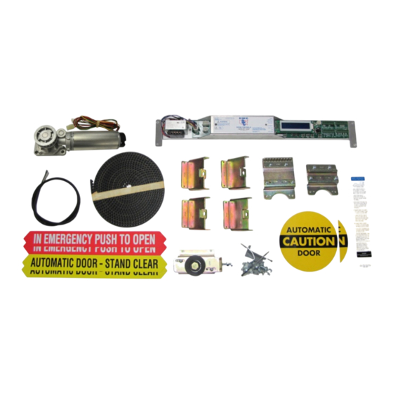
Page 4: Components
Remove the entire existing drive system from the header (motor/gearbox, control, interface, belt, chain, cables, etc.). Do not throw away any mounting hardware as it may be used to mount the DC One components (see drawings). BOX CORES and USED COMPONENTS (motor/gearbox, control, etc.) use the return shipping label and ship to Door Controls. -
Page 5: Wiring Of Accessories
Perform a factory reset – Refer to Sections 12 and 13. Press the TEST button on the DC One control to trigger an activation cycle. When the learn cycle is complete, normal operation will resume according to default values set in the control. Fine-tuning of the ... -
Page 6: Safety Test And Documentation
SAFETY TEST AND DOCUMENTATION When all DC One and sensor adjustments are complete, perform a thorough safety test to validate proper and safe performance in accordance with current ANSI A156.10 guidelines as well as recommendations prescribed by the American Association of Automatic Door Manufacturers (AAADM). -
Page 7: I/O Connector Layout And Description
Holds the door in the open position Green LED is on when active Reset • Resets position values Door will relearn on next activation Yellow LED is on when active DC One V3 Installation Manual Page 5 of 15 M-0015 REV 06222017 P10... -
Page 8: How To Enter Program Mode
Door activates with emergency open and activation input only (pin 2 or 6 of J7) Yellow LED is on when active J8 – Lock Pins 1 to 6 are used to control the DC One lock • Lock voltage is selectable between 12 and 24 volts with toggle switch •... -
Page 9: Menu Display Screens
Indicates the total number of door cycles on the control • Non-resettable • Trip Cycle Counter TRIP CYCLE COUNT 00000000 Indicates the number of cycles since the trip counter was last reset • DC One V3 Installation Manual Page 7 of 15 M-0015 REV 06222017 P10... - Page 10 SELECT MOTOR TYPE DC ONE V3 Adjustable in program mode only • Phone Number DOOR CONTROLS 800-437-3667 Software Version DC ONE V3 FIRMWARE V 1.15 DC One V3 Installation Manual Page 8 of 15 M-0015 REV 06222017 P10...
- Page 11 • Higher values cause a more abrupt change between the two speeds • Ranges from 0 to 255 • Adjustable in or out of program mode • DC One V3 Installation Manual Page 9 of 15 M-0015 REV 06222017 P10...
- Page 12 • Adjustable in program mode only • Hold Open Time HOLD OPEN TIME Ranges from 1 to 30 seconds • Adjustable in program mode only • DC One V3 Installation Manual Page 10 of 15 M-0015 REV 06222017 P10...
- Page 13 • Adjustable in program mode only • Lock Type FAIL SECURE LOCK Sets the lock type to either secure or safe, auto detects DC One lock • Adjustable in program mode only • Breakout Polarity BREAKOUT POLARITY NO Configures breakout for either normally open (NO) or normally closed (NC) contacts •...
-
Page 14: Part Numbers
400 lbs (200lbs per panel for bi-part) Operating Environment -4F to 158F (-20C to +70C) 30% to 85% Relative Humidity 16. WARRANTY TERMS 1 Year from date of purchase from Door Controls USA, Inc. DC One V3 Installation Manual Page 12 of 15... -
Page 15: Trouble Shooting Tips
17. TROUBLE SHOOTING TIPS Before wiring any sensors into the DC One control, it is a good idea to apply power and test the door to ensure it will power open and closed when the TEST button is pressed. -
Page 16: Wiring Diagrams
6 Reset 6 Solenoid + 7 24 VAC 7 NC 8 24 VAC Return 8 NC 9 Common + 9 NC x 10 Safety x 10 NC DC One V3 Installation Manual Page 14 of 15 M-0015 REV 06222017 P10... - Page 17 ORANGE x PURPLE BROWN BLACK x BLACK PURPLE YELLOW x 10 x On Stanley Duraglide replace label for function switches with the one included in kit (DC-3392). DC One V3 Installation Manual Page 15 of 15 M-0015 REV 06222017 P10...
- Page 20 Door Controls USA, Inc. 321 VZ County Road 4500 Ben Wheeler, TX 75754 Phone: 1-800-437-3667 Fax: 1-800-356-8858 Email: Parts@DoorControlsUSA.com DoorControlsUSA.com...
Need help?
Do you have a question about the DC One and is the answer not in the manual?
Questions and answers