Table of Contents
Advertisement
Current Tools
Model #100
™
10,000 lb. Capacity
Mobile Cable Pulling Package
with Patented
Patent #9,899,811
Operating, Maintenance, Safety
and Parts Manual
7/2018
Read and understand this material before operating or
servicing the Cable Puller or any component of the Cable
Pulling Package. Failure to understand how to safely operate
and service these units may result in serious injury or death.
This manual is free of charge. All personnel who operate the Cable Puller or any
component of the Cable Pulling Package should have a copy of this manual and read
and understand its contents. To request a copy of this manual or replacement safety
decals, or for technical assistance, call, write to the address below or visit our website.
CURRENT TOOLS • P. O. BOX 17026 GREENVILLE, SC 29606
800.230.5421 or 864-721-4230 • FAX 864-721-4232
www.currenttools.com
Advertisement
Table of Contents

Related Manuals for Current Tools RotaBoom 100

Summary of Contents for Current Tools RotaBoom 100
- Page 1 To request a copy of this manual or replacement safety decals, or for technical assistance, call, write to the address below or visit our website. CURRENT TOOLS • P. O. BOX 17026 GREENVILLE, SC 29606 800.230.5421 or 864-721-4230 • FAX 864-721-4232...
-
Page 2: Table Of Contents
TABLE OF CONTENTS Safety Alerts ..................3 Important Safety Information ............. 4–7 Major Components ................8 Grounding Instructions ..............9 Assembly Instructions ..............10-15 Common Set-Ups ................16 Transport Information ..............17 Floor/Chain Mount ..............18-22 Specifications and Features .............23-24 MODEL 1450 CABLE PULLER Cable Pulling Basics ............ -
Page 3: Safety Alerts
SAFETY ALERTS Safety Alert Symbol THIS SAFETY SYMBOL is used to call your attention to instructions that concern your personal safety. It means: ATTENTION! BE AWARE! THIS IS AN IMPORTANT SAFETY INSTRUCTION! Read, understand, and follow these safety instructions. Failure to follow these safety instructions may result in injury or death. -
Page 4: Important Safety Information
RETAIN SAFETY INFORMATION This manual should be read and understood by all personnel who operate or service this Puller. Failure to understand how to safely operate and service this unit could result in serious injury or death. This unit should only be operated and serviced by qualified personnel. - Page 5 DANGER IMPORTANT SAFETY INFORMATION — CONTINUED DANGER WARNING Pulling Rope should be the only thing to contact the capstan. NEVER let swivels, grips, etc. come in contact with the capstan. DANGER WARNING Keep as much rope confined in conduit as possible. This will help CAUTION prevent injury should the rope break and whip violently.
- Page 6 DANGER IMPORTANT SAFETY INFORMATION — CONTINUED WARNING Rope should approach DANGER SIDE capstan as shown in VIEW Figure 6a CAUTION WARNING ALWAYS use black roller MAXIMUM to guide rope so that the 10˚ operator stands at a 90˚ PULL CAUTION angle to the cable puller DIRECTION and out of the direct line...
-
Page 7: Important Safety Information
IMPORTANT SAFETY INFORMATION — CONTINUED WARNING When using the Model #2281 chain mount, never tighten chain as shown in Figure A. This causes side loading of the chain and can result in failure of the chain or screw causing components to come loose and possibly cause serious injury or death. -
Page 8: Major Components
MAJOR COMPONENTS — MODEL #100 ITEM # CATALOG # DESCRIPTION WEIGHT 1450 Cable Puller – 10,000 lb Capacity 119 lbs. 1710 Elbow Unit 43 lbs. 1840 (optional) Nose Unit 33 lbs. 1840-S Nose Unit with Sheave 34 lbs. 1000 Mobile Carriage 75 lbs. -
Page 9: Grounding Instructions
GROUNDING INSTRUCTIONS WARNING ELECTRIC SHOCK HAZARD! Only connect the Model 1450 Puller to a 20 amp GFCI protected circuit. DO NOT modify the plug that is provided with the unit. Failure to follow these warnings can result in serious injury or death. RECEPTACLE PLUG Figure 9... -
Page 10: Assembly Instructions
ASSEMBLY INSTRUCTIONS Planning the Pull WARNING Some components weigh more than 50 lbs. and will require more than one person to lift, transport and assemble. 1. Referring to the major components list on page 8 make sure you have all the components necessary to build a complete package. - Page 11 ASSEMBLY INSTRUCTIONS — CONTINUED Slip-In Couplings Used to Straddle Conduit Slip-In Couplings can be used to straddle the conduit. One advantage of this is the couplings can be straddled on conduit sizes smaller than 2 1/2". However, the largest conduit you can straddle using a slip-in coupling is 5" (by using the 6"...
- Page 12 ASSEMBLY INSTRUCTIONS — CONTINUED Screw-On Couplings Screw-On Couplings, which thread onto the end RECEIVER of Rigid or IMC conduit, are optional for conduit PLATE sizes 2", 2 1/2", 3", 3 1/2" and 4". ( TURN TO FACE CABLE PULLER ) Screw-On Couplings Procedure: 1.
- Page 13 NOTE: When using pipe other than the boom tubes supplied by Current Tools, fully insert the pipe or conduit and install a 1/2-13 × 2" Threaded bolt (user provided) into the threaded nut on the side of the receiver tube and tighten against the boom tube.
- Page 14 ASSEMBLY INSTRUCTIONS — CONTINUED 2. If only one boom tube is needed, slide the Model #1840-S nose unit (or #1840 optional nose unit) onto the boom tube you installed in Step #1. (See Photo 14a). Determine the type of pull to be made (up pull, down pull, side pull) and turn the nose unit accordingly.
- Page 15 ASSEMBLY INSTRUCTIONS — CONTINUED Sight Hole Elbow Unit Angle Adjustment Pin If more reach is needed, an extra boom tube is provided. To install, continue assembly instructions as follows: NOTE: The extra boom tube can be stored on the lower half of the carriage frame and secured with the provided locking screw.
-
Page 16: Common Set-Ups
COMMON SET UPS WARNING When using one boom tube and nose unit, factory supplied boom tube may be replaced but must meet the following specifications: • Only use 3" schedule 40 pipe or 3" rigid conduit 3' min. to 10' max. •... -
Page 17: Transport Information
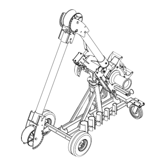
TRANSPORT INFORMATION The Mobile Carriage is designed to easily move the Pulling Assembly from location to location. To Prepare for Transport Before moving, use the boom height adjustment handle and raise the boom tube as shown in Figure 17. If both sections of the standard boom tubes are installed, remove the elbow unit angle adjustment pin and rotate the forward... -
Page 18: Floor/Chain Mount
FLOOR/CHAIN MOUNT The Model #2280 floor mount and #2281 chain mount are made to fit the Current Tools Model #1450 Cable Puller and can be mounted using two different procedures as noted on pages 18 through 22. PROCEDURE #1 Mounting to a concrete floor... - Page 19 FLOOR/CHAIN MOUNT — CONTINUED The pulling direction should ALWAYS be parallel to the base of the floor mount. See Figure 19. CORRECT PULLING DIRECTION Figure 19 mounting chain handle hole capstan mounting chain Installation Instructions handle hole floor mount holes (4 places) 1.
- Page 20 FLOOR/CHAIN MOUNT — CONTINUED Floor Mount Anchor Holes Installing Puller on Floor Mount Figure 20a Figure 20b Tandem Pulling If the amount of pulling force required to make a pull exceeds the load rating for a single cable puller, two cable pullers may be used in tandem to make the pull.
- Page 21 FLOOR/CHAIN MOUNT — CONTINUED PROCEDURE #2 Mounting Chain Instructions (Model #2281 chain mount) The Model #2281 chain mount is designed to be secured to conduit or structural supports using the two chains provided. The handles on the chains should provide sufficient leverage to tighten the chains securely. No other tools are needed.
-
Page 22: Floor/Chain Mount
FLOOR/CHAIN MOUNT — CONTINUED CAPSTAN MOUNTING CHAIN HANDLE HOLE Figure 22 PULLER MOUNT PINS NOTE: Install Model #1450 puller onto the chain mount by lowering the puller over the chain mount and inserting the puller mount pins (See Figure 22). Secure the puller mount pins with spring clips. -
Page 23: Specifications And Features
FEATURES • One person set up • Patented 45 degree horizontal pivot allows for use of puller in tight spaces. See drawing below. • Built-in force gauge with digital read out and color screen to indicate force ranges • Circuit breaker on/off switch — helps protect motor •... - Page 24 FEATURES — MODEL 1450 CABLE PULLER On/Off Circuit Breaker Switch Carry Handles High/Low Speed Switch Digital Force 20 Amp Motor Gauge Tapered Capstan Puller Ready Light Safety Roller...
-
Page 25: Model 1450 Cable Puller
CABLE PULLING BASICS Model 1450 Cable Puller and Accessories The Model 1450 Cable Puller has a maximum pulling force of 10,000 lbs. Therefore, all of the accessories used to make a cable pull with this unit must be rated to meet or exceed the forces generated. -
Page 26: Cable Pulling Basics
CABLE PULLING BASICS — CONTINUED Model 1450 Cable Puller — mounting to Model 1190 Puller Mount. -
Page 27: Operating Instructions
OPERATING INSTRUCTIONS — MODEL 1450 CABLE PULLER DO NOT operate cable puller in wet or damp locations. Do NOT expose to rain. DO NOT operate in an explosive atmosphere. DO NOT use cable puller as a hoist or for lifting, supporting or transporting people or loads. - Page 28 OPERATING INSTRUCTIONS — CONTINUED WARNING OPERATING INSTRUCTIONS — CONTINUED Rope should approach capstan as shown in Figure 27b. ALWAYS use black roller to guide rope so that operator stands at 90° angle to the cable puller and out of the direct line of tight pulling rope. See Figure 27a.
- Page 29 OPERATING INSTRUCTIONS — CONTINUED 5. Once the puller ready light mounted in the electronics box is lit, depress the foot switch to activate the puller. As the rope is tailed, it should mound on the floor between the operator and the cable puller. 6.
- Page 30 OPERATING INSTRUCTIONS — CONTINUED WARNING Rope must ALWAYS be pulled over a rotating sheave. If a sheave does not rotate, turn cable puller off immediately and determine the problem before continuing the pull. WARNING Pulling Rope should be the only thing to contact the capstan. NEVER let swivels, grips, etc.
-
Page 31: Maintenance
MAINTENANCE WARNING Unplug the cable puller before servicing. DO NOT alter this cable puller. Doing so will void the warranty. Guards and safety features are provided for your protection. Capstan Replace the capstan if it is grooved more than 1/16” deep. Lubrication Wheels and casters —... -
Page 32: Exploded Views And Parts Lists - Model 1450
EXPLODED VIEW – MODEL 1450 CABLE PULLER PARTS LIST – MODEL 1450 CABLE PULLER ITEM # PART # DESCRIPTION QTY. 66-38 KEY-SQUARE (3/8" × 1.25" LG) 77-044 RIVET, ALUM, BUTTONHEAD (1/8" .08-.120 GRIP) 88-59 WASHER - 11 GA HRPO ZINC (.630ID × 2.25OD) 88-18 ROLLER –... - Page 33 EXPLODED VIEW – MODEL 1450 ELECTRONICS BOX ASSEMBLY PARTS LIST – MODEL 1450 ELECTRONICS BOX ASSEMBLY ITEM # PART # DESCRIPTION QTY. 100-002 CIRCUIT BOARD 100-003 METER 100-004 RELAY 100-008 RELAY 100-030 TOGGLE SWITCH 100-031 TIMER 100-280 CORD – FOOT SWITCH, 8' 100-033 LIGHT –...
- Page 34 EXPLODED VIEW – MODEL 1450 CABLE PULLER GEAR MOTOR...
- Page 35 PARTS LIST – MODEL 1450 GEAR MOTOR ITEM # PART # DESCRIPTION QTY. 1000-137 BRUSH ASSEMBLY WITH CAPS 1000-138 FLANGE NUT 1000-139 HEYCO STRAIN RELIEF, BLACK, #1287 1000-140 COMM ENDBELL ASSEMBLY 1000-141 3 WAVE SPRING (SSB-0138) 1000-142 MOTOR FRAME 1000-143 115V ARMATURE AND BEARING ASSEMBLY 1000-144 1ST STAGE GEAR (PINION) MACHINED/SNAP RINGS (2)
-
Page 36: Wiring Diagram - Model 1450
WIRING DIAGRAM – MODEL 1450 CABLE PULLER... -
Page 37: Components Parts Listing
COMPONENT PARTS LISTING SCREW-ON COUPLINGS ITEM # PART # DESCRIPTION QTY. SCREW-ON COUPLING FOR 2" IMC, RIGID CONDUIT optional SCREW-ON COUPLING FOR 2 1/2" IMC, RIGID CONDUIT optional SCREW-ON COUPLING FOR 3" IMC, RIGID CONDUIT optional SCREW-ON COUPLING FOR 3 1/2" IMC, RIGID CONDUIT optional SCREW-ON COUPLING FOR 4"... - Page 38 COMPONENT PARTS LISTING — CONTINUED FOUR WHEEL CARRIAGE – 1000 ITEM # PART # DESCRIPTION QTY. 77-016 PIN – COTTER, 3/16" × 1 1/4" 77-017 WASHER – FLAT 3/4 SAE 77-429 AXLE 100-027 BUSHING – BASE 100-273 FRAME – CARRIAGE 452-27 WASHER –...
- Page 39 COMPONENT PARTS LISTING — CONTINUED (optional) NOSE UNIT – 1840 ITEM # PART # DESCRIPTION QTY. 33-22 SPRING – COUPLING MOUNT PAWL 33-485 PAWL – COUPLING MOUNT 100-011 BOOM PIN SPRING 100-170 BOOM PIN 100-172 NOSE UNIT OUTER 100-173 NOSE UNIT COUPLING ADAPTER 100-182 NOSE UNIT CUP ADAP ROLLER PIN 100-203...
- Page 40 COMPONENT PARTS LISTING — CONTINUED FLOOR MOUNT – 2280 CHAIN MOUNT – 2281 ITEM # PART # DESCRIPTION QTY. 100-231 FLOOR MOUNT FRAME CHAIN MOUNT HANDLE 88-42 ITEM # PART # DESCRIPTION QTY. ASSEMBLY 100-231 FLOOR MOUNT FRAME CHAIN MOUNT CHAIN 88-21L 8045-3 WEDGE ANCHOR...
-
Page 41: Components Parts Listing
COMPONENT PARTS LISTING — CONTINUED WORM BOX ASSEMBLY – 100-156 ITEM # PART # DESCRIPTION QTY. 2-1504-4 NUT-HEX NYLON INSERT (3/8-16) 100-006 PLASTIC HANDLE 100-026 7/8 RETAINING RING – EXTERNAL 100-012 THRUST BEARING 100-013 THRUST RACE 100-016 WORM GEAR 100-233 WORM HANDLE WELDMENT 100-269 KEYSTOCK 3/16"...
Need help?
Do you have a question about the RotaBoom 100 and is the answer not in the manual?
Questions and answers