Table of Contents
Advertisement
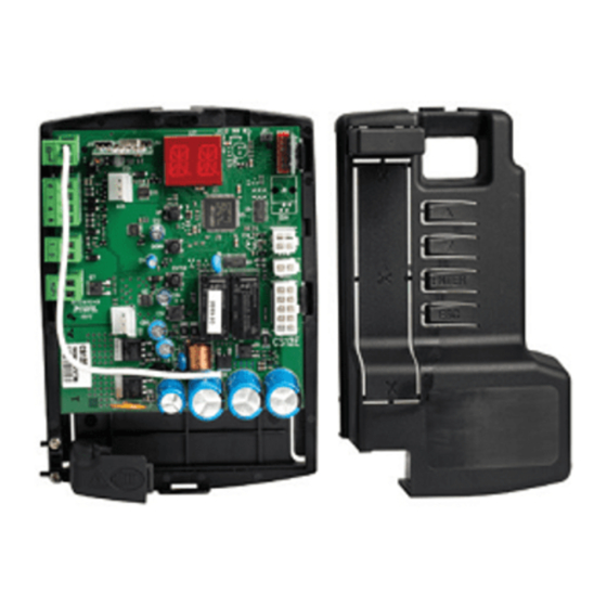
Entrematic CS12E
Control panel installation manual for Ditec NEOS automations
Antenna
-
Output 24 V max 0,3 A
+
Safety stop
Closing safety device
Step-by-step
Flashing light
JR3
AUX
UP
DOWN
ENTER
ESC
www.entrematic.com
IP2162EN • 2018-09-06
COM
JR1
NES100FCM
LSW
NES100BBU
BAT
Selection of automation type
(FACTORY SET)
blue
+
Power supply
24V
black
-
MOTOR
Release
microswitch
Advertisement
Table of Contents

Summary of Contents for Ditec Entrematic CS12E
- Page 1 Entrematic CS12E IP2162EN • 2018-09-06 Control panel installation manual for Ditec NEOS automations Antenna Output 24 V max 0,3 A Safety stop Closing safety device NES100FCM DOWN Step-by-step NES100BBU Flashing light ENTER Selection of automation type (FACTORY SET) blue Power supply...
-
Page 2: Table Of Contents
Index Subject Page General safety precautions EC Declaration of Conformity Technical specifications Commands Inserting plug-in card (AUX) Self-controlled safety edge Outputs and accessories Selections Settings Switching on and off Key combinations Main menu Second level menu - AT (Automatic Configurations) Second level menu - BC (Basic Configurations) Second level menu - BA (Basic Adjustment) Second level menu - RO (Radio Operations) -
Page 3: General Safety Precautions
1. General safety precautions Failure to observe the information given in this manual may lead to personal injury or damage to the equipment. Keep these instructions for future reference This installation manual is intended for qualified personnel only. Installation, electrical connections and adjustments must be performed in accordance with Good Working Methods and in compliance with the present standards. -
Page 4: Ec Declaration Of Conformity
2. EC Declaration of Conformity The manufacturer Entrematic Group AB, with headquarters in Lodjursgatan 10, SE-261 44 Land- skrona, Sweden, declares that the Entrematic CS12E type control panel complies with the conditions of the following EC directives: 2014/30/EU (EMCD) -
Page 5: Commands
4. Commands Command Function Description 5 NO STEP-BY-STEP When selecting → → , closing the con- WITH AUTOMATIC tact starts a sequential opening or closing operation: CLOSING opening-stop-closing-opening. WARNING: if automatic closing is enabled, the dura- tion of the stop can be selected by selecting →... -
Page 6: Inserting Plug-In Card (Aux)
4.1 Inserting plug-in card (AUX) To access the plug-in card (AUX), cut the control panel cover as shown in the figure. DOWN ENTER 4.2 SOFA1-SOFA2 or GOPAVRS self-controlled safety edge Command Function Description SAFETY TEST Place the SOFA1-SOFA2 or GOPAVRS device into the SOFA1-SOFA2 special housing for AUX plug-in cards. - Page 7 Examples of installation of self-controlled safety edge SOFA15 SOFA20 SOFA25 SOFA15 SOFA20 SOFA25 OPENING GOPAVT SOFA15 SOFA15 SOFA20 SOFA20 SOFA25 SOFA25 IN1 IN2 +BC OPENING...
-
Page 8: Outputs And Accessories
5. Outputs and accessories Value Output Description Accessories Accessories power supply. External accessories power supply output. 24 V 0.3 A N.B.: the maximum absorption of 0.3 A corresponds to the sum of all terminals 1. Antenna connection (433, 92 MHz). GOL148REA If the inside radio receiver is used, connect the supplied antenna (433, 92 MHz) -
Page 9: Selections
6. Selections Jumper Description Display mode selection. Display mode. Maintenance mode. Only the v alues and pa- Only the v alues and pa- rameters present can be rameters present can be displayed. displayed and modified. G oing into maintenance mode is indicated by the permanent switching on of the right-hand point on the display. -
Page 10: Key Combinations
Key combinations • Simultaneous pressing of the keys ↑and ENTER performs an opening com- mand. • Simultaneous pressing of the keys ↓and ENTER performs a closing command. • Simultaneous pressing of the keys ↑ and ↓ performs a POWER RESET com- mand. -
Page 11: Main Menu
Main menu • using keys ↑ and ↓ select the desired function • press the ENTER key to confirm After confirming the selection, you access the second level menu. Display Description AT - Automatic Configurations. The menu allows you to manage the automatic configurations of the control panel. -
Page 12: Second Level Menu At (Automatic Configurations)
Second level menu AT (Automatic Configurations) • using keys ↑ and ↓ select the desired function • press the ENTER key to confirm Display Description RT - Opening to right. LF - Opening to left. H0 - Predefined setting, residential use 0. This selection loads predefined values for certain standard parameters: AC - enabling of automatic closing : disabled... - Page 13 Display Description AA - Activating advanced parameters menu. → 2” After activation you can scroll through the third level menus. The third level menus are activated for 30 min. Depending on the type of automation and control panel, some menus may not be available.
-
Page 14: Second Level Menu - Bc (Basic Configurations)
Second level menu - BC (Basic Configurations) • using keys ↑ and ↓ select the desired function • press the ENTER key to confirm Display Description AC - Enabling of automatic closing. ON - Enabled OF - Disabled SS - Selection of automation status at start. OP - Open CL - Closed Indicates how the control panel considers the automa-... - Page 15 7.5.1 Additional BC level parameters that can be configured (available with → enabled) Display Description HR - Enabling of operator present function ON - Enabled OF - Disabled N.B.: Set → only if → → 64 - Functioning of safety stop/closing command. 1-4 - Closing 1-6 - Safety stop C5 - Step-by-step/opening command operation.
-
Page 16: Second Level Menu - Ba (Basic Adjustment)
Second level menu - BA (Basic Adjustment) • using keys ↑ and ↓ select the desired function • press the ENTER key to confirm Display Description MT - Display of type of automation. N3 - Motor with 300 kg capacity N4 - Motor with 400 kg capacity N6 - Motor with 600 kg capacity SF - Motor Super Fast with 600 kg capacity... - Page 17 Display Description VC - Setting of closing speed. [cm/s] N.B.: 24 - Maximum with → 25 - Maximum with → 40 - Maximum with → Neos Super Fast R2 - Adjustment of thrust on obstacles and current during opening [%] The control panel is equipped with a safety device that stops movement if an obstacle is detected during an opening operation with disengagement of 10 cm.
- Page 18 7.6.1 Additional BA level parameters that can be configured (available with → enabled) Display Description DT - Adjustment of obstacle recognition time. [s/100] 10 - Minimum 60 - Maximum N.B.: the parameter is adjusted in hundredths of a second. MP - Start at maximum power ON - During start-up it increases the thrust on obsta- cles to maximum.
- Page 19 Display Description OB - Adjustment of deceleration distance during closing. [cm] Indicates the distance from the end of the closing stroke where the deceleration ramp begins. 05 - Minimum , (20 - Neos Super Fast) Neos Super Fast 99 - Maximum N.B.: reduce the deceleration space if there is a series of quick vibrations (chattering) in heavy gates installed with a slight incline.
-
Page 20: Second Level Menu - Ro (Radio Operations)
Second level menu - RO (Radio Operations) • using keys ↑ and ↓ select the desired function • press the ENTER key to confirm Display Description SR - Remote control storage. You can directly access the Remote control storage menu even with the dis- play turned off, but only with the Display visualisation mode option set to 00 or 03: - for transmitting a remote control not present in the memory;... - Page 21 Display Description RK - Menu navigation using remote control keyboard ON - Enabled OF - Disabled With the display turned off, quickly type in the sequence of keys 3 3 2 4 1 from the stored remote control you want to use.
- Page 22 7.7.1 Additional RO level parameters that can be configured (available with → enabled) Display Description C1, C2, C3, C4 - Selection of CH1, CH2, CH3, CH4 func- tion of stored remote control. NO - No setting selected 1-3 - Opening command 1-4 - Closing command 1-5 - Step-by-step command P3 - Partial opening command...
-
Page 23: Second Level Menu - Sf (Special Functions)
Second level menu - SF (Special Functions) • using keys ↑ and ↓ select the desired function • press the ENTER key to confirm Display Description CU - Displaying the control panel firmware version. Release 1.1 [esempio] (example) → → →... - Page 24 7.8.1 Additional SF level parameters that can be configured (available with → enabled) Display Description SP - Setting the password. → → → → → 2” [esempio] (example) N.B.: this can only be selected when the password is not set. Setting the password prevents unauthorised personnel from accessing se- lections and adjustments.
-
Page 25: Second Level Menu - Cc (Cycles Counter)
Second level menu - CC (Cycles Counter) • using keys ↑ and ↓ select the desired function • press the ENTER key to confirm Display Description CV - Display of total operations counter. 182 manovre [esempio] operations (example) → → →... - Page 26 7.9.1 Additional CC level parameters that can be configured (available with → enabled) Display Description CA - Setting the maintenance alarm. You can set the required number of operations (regarding the partial opera- tions counter) for signalling the maintenance alarm. When the set number of operations is reached, the alarm message appears on the display →...
-
Page 27: Second Level Menu - Ap (Advanced Parameters)
7.10 Second level menu - AP (Advanced Parameters) • using keys ↑ and ↓ select the desired function • press the ENTER key to confirm Display Description FA - Selection of opening limit switch mode. NO - None SX - Stop limit switch (after activation the door wing stops its movement) PX -... - Page 28 Display Description DS - Setting of display visualisation mode. 00 - No display 01 - Commands and safety devices with radio test (see paragraph 8.2). Display of count down to automatic closing. 02 - Automation status (see paragraph 8.1) 03 - Commands and safety devices (see paragraph 8.2) WARNING: depending on the type of automation and control panel, some menus may not be available.
- Page 29 7.10.1 Additional AP level parameters that can be configured (available with → enabled) Display Description DO - Setting of disengagement on stop during open- ing. [mm] 00 - Minimum 10 - Maximum N.B.: Not active if → DC - Setting of disengagement on stop during clos- ing.
- Page 30 Display Description TN - Setting of intervention temperature for NIO anti- freeze system. [°C] Adjustment of the working temperature of the control pan- el. The value does not refer to ambient temperature. TB - Display of working temperature of control panel. DO NOT USE WO - Setting of pre-flashing time on opening.
-
Page 31: Display Visualisation Mode
8. Display visualisation mode WARNING: depending on the type of automation and control panel, some menus may not be available. Display of automation status The automation status display mode is only visible with Display visualisation mode set to 02. → →... - Page 32 Display Description → Automation closed. Automation closed. Release door open. Automation open. Automation open. Release door open. Automation stopped in intermediate position. Automation stopped in intermediate position. Release door open. Automation closing. Automation that slows down during closing. Automation opening. Automation that slows down during opening.
-
Page 33: Display Of Safety Devices And Commands
Display of safety devices and commands The safety device and command display mode is only visible with Display visualisation mode set to 01 or 03. → → → → Display Description 1-3 - Opening command. 1-4 - Closing command. 1-5 - Step-by-step command. 1-6 - Safety device with opening and closing stop. - Page 34 CX - Receipt of command from AUX card. F1 - Closing limit switch F2 - Opening limit switch O1 - Detection of an obstacle during closing O2 - Detection of an obstacle during opening OO - Reaching of obstacle detection limit during opening OC - Reaching of obstacle detection limit during closing S1 - Detection of stop during closing S2 - Detection of stop during opening...
-
Page 35: Display Of Alarms And Faults
Display of alarms and faults Alarms and faults can be displayed with any display selection. The signalling of alarm messages takes priority over all other displays. Type of Display Description Operation alarm M0 - Selected motor not suitable. Set correct motor wiring. M3 - Automation blocked (open/closed) Check the mechanical parts M4 - Motor short circuit Check the motor is correctly con-... - Page 36 Type of Display Description Operation alarm R3 - Storage module not detected (with Insert a working storage module or set JR3=ON). JR3=OFF. R5 - Storage module not working (re- Replace the storage module. gardless of JR3) A0 - Failure of test of safety sensor on Check that device SOFA1-A2/GOPAV is contact 6.
- Page 37 Type of Display Description Operation alarm IM - Shortcircuited motor MOSFET Reset. alarm If the problem persists, contact Tech- nical Support. IO - Interrupted power circuit (motor Reset. MOSFET open) If the problem persists, contact Tech- nical Support. IR- Motor relay malfunctioning Reset.
-
Page 38: Start-Up
Start-up WARNING The operations related to point 5 are performed without safety devices. The display parameters can only be adjusted when the automation is idle. The automation automatically slows when approaching the end stops or stop limit switches. At every start-up the control panel receives a RESET and the first opera- tion is performed at reduced speed (automation position acquisition). -
Page 39: Troubleshooting
10. Troubleshooting Problem Possible cause Alarm Operation signalling The automation does not No power. Check power supply cable. open or close. Short circuited accessories. Disconnect accessories from terminals 0-1 (a voltage of 24V= must be present) and reconnect them one at a time. Contact Technical Service Blown line fuse. - Page 40 The automation opens/clos- There is a presence of friction. Manually check that the auto- es briefly and then stops. mation moves freely and check adjustment Contact Technical Service The remote control has lim- The radio transmission is im- Install the antenna outside. ited range and does not work peded by metal structures and with the automation moving.
-
Page 41: Examples Of Application
11. Examples of sliding gate applications When the CS12E control panel is used for sliding automation applications, the following connections can be made: - set the correct opening direction: x2 s x2 s Example 1 - Door wing stops against mechanical end stops (standard setting) - Page 42 All the rights concerning this material are the exclusive property of Entrematic Group AB. Although the contents of this publication have been drawn up with the greatest care, Entrematic Group AB cannot be held responsible in any way for any damage caused by mistakes or omissions in this publication. We reserve the right to make changes without prior notice.
Need help?
Do you have a question about the CS12E and is the answer not in the manual?
Questions and answers