Advertisement
Quick Links
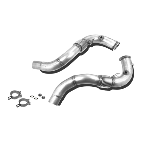
N63 N63TU DOWNPIPES INSTALLATION GUIDE
TOOLS: 6mm Socket, 8mm Socket, 11mm Socket, 13mm Deep Socket, 15mm Deep Socket
O2 Sensor Socket, 6mm Hex Socket/Allen Key, E8 External Torx, E10 External Torx
12" Extension and Swivel Adapter, Adustable Wrench, Flathead Screwdriver, T30 Torx Bit
PHASE 1: REMOVE INTAKE
For those of you lifting the vehicle the old fashioned way this installation will only require the front end
of the car to be lifted off of the ground. That said,
never work on a car being supported only by a jack.
Always utilize jack stands that meet the weight requirements of your vehicle.
Advertisement

Related Manuals for ARM Motorsports N63TU

Summary of Contents for ARM Motorsports N63TU
- Page 1 N63 N63TU DOWNPIPES INSTALLATION GUIDE TOOLS: 6mm Socket, 8mm Socket, 11mm Socket, 13mm Deep Socket, 15mm Deep Socket O2 Sensor Socket, 6mm Hex Socket/Allen Key, E8 External Torx, E10 External Torx 12" Extension and Swivel Adapter, Adustable Wrench, Flathead Screwdriver, T30 Torx Bit...
- Page 2 STEP 1: Remove the factory engine cover by pulling up on the anchor points. There is one at the front of the engine and two near the back. STEP 2: With the factory intake exposed we will need to loosen the 6mm clamp on the intake hose on each side.
- Page 3 STEP 3: Disconnect the airflow sensor on each side of the intake by pressing the tab and pulling away. Leave the sensor inserted in the air filter box to protect it. STEP 4: Disconnect the lower air tube on the air filter box. This is can be done by using a flat head screwdriver to pull the plastic away from the clip shown in the image.
- Page 4 STEP 5: Undo the clasp holding in the portion of the intake with the orange rubber grommet on it by using your flathead screwdriver. STEP 6: We can now disconnect the four O2 sensor connections and remove the harness's from the clips around the intake box.
- Page 5 STEP 7: With the air filter box now unattached to anything we can remove it by pulling up to pop it off of the mounts holding it on underneath. PHASE 2: REMOVE FACTORY DOWNPIPES STEP 8: Remove the metal bracket on the top of the engine by using a deep 13mm socket to loosen the bolt on each side.
- Page 6 STEP 9: Disconnect the topside O2 sensors using an O2 sensor socket and remove them and their copper cups. STEP 10: We'll begin removing the heat shield by loosening the 3 E8 sized external torx bolts on each side. It is helpful to have an extension for this.
- Page 7 STEP 11: There are an additional 3 on the back side. In total there are 9 bolts which need to be removed. Once they are removed the heat shield can be lifted out. STEP 12: Uninstall the 3 bolt brace on each downpipe using a 6mm hex socket.
- Page 8 STEP 13: There are another two 6mm hex bolts on each side holding the downpipe to the back of the engine which need to be removed. STEP 14: Remove the vband clamps holding the downpipes to the turbos using a 13mm socket.
- Page 9 STEP 15: Using an adjustable wrench loosen and remove the lower O2 sensor on each side. STEP 16: Going underneath the vehicle we are going to remove the first portion of the undertray using an 8mm socket.
- Page 10 STEP 17: With this section of the undertray removed the metal splash guard is exposed. This is held on with 13mm bolts. When all the bolts are removed slide it towards the rear of the vehicle for it to drop out.
- Page 11 STEP 19: Now we have access to the clamp connecting the downpipe to the midpipe. Use a deep 15mm socket to loosen this on each side. STEP 20: Next loosen the brace holding up the midpipes. Use a 13mm socket to loosed one side of the brace.
- Page 12 STEP 21: Remove the two E10 external torx bolts holding the brace up. STEP 22: There is another bracket on the lower side of the downpipe which is fastened using two 11mm nuts. Remove these two nuts on each side by using a long extension (at least 1ft) to reach in at a shallow angle.
- Page 13 STEP 23: With these nuts removed this bracket now needs to be pulled off the bolts it was connected to. It may be required to use a long flathead screwdriver or small pry bar to do this. STEP 24: Next slide the downpipes from the midpipe. If the connection is corroded it will help to tap it with a rubber mallet or hammer to break it free.
- Page 14 STEP 25: Now that the downpipes are fully disconnected they must be pulled out from the top. To make room for them we will remove the heat shield and plastic housing at the back of the engine bay by pulling the rubber lining away and removing the three 8mm screws and two T30 torx bolts. STEP 26: The downpipes can now be removed using a twisting method.
- Page 15 PHASE 3: INSTALL ARM CATLESS DOWNPIPES STEP 27: Once the factory downpipes are removed the hardest part is over. We can now install the ARM downpipes in reverse order. Passenger side first, then driver side. STEP 28: Place the new ARM Crush Bracket on each downpipe. Make sure they are oriented so that the smaller of the two angles between the bracket and clamp bolt is positioned towards the front of the car.
- Page 16 STEP 29: Insert the downpipes back into the midpipe completely, but leave the clamp loose. STEP 30: Reinstall and secure the midpipe bracket with E10 external torx and 13mm bolt.
- Page 17 STEP 31: Reinstall the lower O2 sensors while the top of the downpipe is still loose. These should have the mesh seals and round connectors while the O2 sensors on the top of the downpipe have the oval shaped connectors. STEP 32: Connect the v band flange around the downpipes and turbos.
- Page 18 STEP 33: Back underneath the car, tighten down the downpipe to midpipe connection ensuring they are fully inserted. STEP 34: Place the ARM Crush Bracket around the lower stud enough to start the supplied 13mm nut on the threads. Alternate between tightening the clamp bolt (15mm) and the bracket nut 2 - 3 turns at a time.
- Page 19 STEP 35: Place one of the supplied washers over the factory 6mm hex bolt and secure the bracket on the backside of the engine on each side. STEP 36: Reinstall the splash guards in reverse order. Sections 1 and 3 using the 8mm screws and the 13mm bolts for the number 2 metal splash guard.
- Page 20 STEP 37: Reinstall the factory heat shield using the nine E8 external torx bolts. STEP 38: Reinstall the O2 sensors on the top of the engine by placing the cups in first. Make sure the arrow of the passenger side cup is pointed at the arrow on the heat shield. Torque the O2 sensors down.
- Page 21 STEP 39: Reinstall the metal bracket on top of the engine using the deep 13mm socket. STEP 40: Reconnect the O2 sensors to their connections and place the wires into their clips.
- Page 22 PHASE 4: REINSTALL THE FACTORY INTAKE SYSTEM STEP 41: Reinstall the factory airboxes onto their grommets. STEP 41: Reconnect the lower air tubes by snapping them into place.
- Page 23 STEP 42: Slide the rubber hose over the upper airbox connection and tighten down the clamps on each side. STEP 43: Reconnect the MAF sensor on the air box.
- Page 24 STEP 44: Reinstall the factory engine cover. CONGRATULATIONS! You’ve finished the installation, now enjoy your new ARM Motorsports Catless Downpipes! If you have any questions please contact us at getarmed@armmotorsports.com.
Need help?
Do you have a question about the N63TU and is the answer not in the manual?
Questions and answers