Table of Contents
Advertisement
Quick Links
Advertisement
Table of Contents

Related Manuals for Newtec M6100


Summary of Contents for Newtec M6100
- Page 1 M6100 User Manual M6100 Broadcast Satellite Modulator R1.4 V1.4...
-
Page 2: Table Of Contents
M6100 Broadcast Satellite Modulator Table of Contents Table of Contents 1 Copyright ......................1 2 EU Compliancy Statements ................2 2.1 Radio and Telecommunications Terminal Equipment (R&TTE) Directive 1995/5/EC ......... 2 2.2 EMC Information ............................3 2.3 Restriction of Hazardous Substances Directive (RoHS) (Directive 2011/65/EU) ........3 2.4 Registration, Evaluation and Authorization of Chemicals (REACH) ............ - Page 3 M6100 Broadcast Satellite Modulator Table of Contents 8 Getting Started ....................27 8.1 Set the Management IP Address ....................... 27 8.2 Set Date and Time ............................. 28 8.3 Configure and Save ........................... 29 9 How to Manage the Device ................30 9.1 Management Model / Menu Tree ......................
- Page 4 M6100 Broadcast Satellite Modulator Table of Contents 9.7.4.1 Show ............................. 62 9.7.4.2 Help ............................... 64 9.7.4.3 Context Sensitive Help "?" ......................64 9.7.5 Navigate Through the Branches of the Device ..................65 9.7.6 Go into a Branch ..........................65 9.7.7 Move Up one Level ..........................65 9.7.8 Return to the Main Branch ........................
- Page 5 M6100 Broadcast Satellite Modulator Table of Contents 10.7 Diagnostics Report ..........................94 10.8 Date and Time ............................96 10.9 Device Monitoring ............................ 98 10.10 Reset the Device ........................... 99 10.11 Alarm Handling ............................ 100 10.11.1 Alarm Masking ..........................101 10.11.2 Alarm Configuration ........................103 10.11.3 Clear Alarm Counters ........................
- Page 6 M6100 Broadcast Satellite Modulator Table of Contents 11.7.3 Program-Specific Information (PSI-SI) Insertion ................137 11.7.4 Traffic Classification, Shaping and Channels .................. 139 11.7.4.1 Traffic Classification ........................140 11.7.4.2 Traffic Shaping .......................... 142 11.7.4.3 Channels ........................... 144 11.8 BBF over IP In ............................146 12 Features Descriptions ..................
- Page 7 M6100 Broadcast Satellite Modulator Table of Contents 12.6 DVB Carrier Identification ........................167 12.6.1 Device Unique ID ..........................167 12.6.2 Device Variable Parameters ......................167 12.6.3 How does it Work? ........................... 168 12.6.4 What to do when Interference is Detected? ..................168 12.7 TS Analyser ............................
- Page 8 M6100 Broadcast Satellite Modulator Table of Contents 12.11.7.3 Changing Keys Seamlessly ..................... 202 12.11.7.4 Removing a Receiver from the Network .................. 202 12.11.7.5 Setting up a Secure BISS Network ..................202 12.11.7.6 Creating Groups of Receivers ....................203 12.11.8 Keys and Redundancy, Backup or Import ..................203 12.11.8.1 BISS and Redundancy ......................
-
Page 9: Copyright
M6100 Broadcast Satellite Modulator Copyright 1 Copyright © August 7, 2014 The material contained in this document is confidential and intended for use only by parties authorized by Newtec Cy N.V. All Rights Reserved. No part of this document may be photocopied, reproduced, stored in a retrieval... -
Page 10: Eu Compliancy Statements
M6100 Broadcast Satellite Modulator EU Compliancy Statements 2 EU Compliancy Statements 2.1 Radio and Telecommunications Terminal Equipment (R&TTE) Directive 1995/5/EC Declare that the following product: • Product number: M6100 • Type identifier: NTC/2353 to which this declaration relates is in conformity with the essential requirements of European Union Directive 1999/5/EC Radio and Telecommunication Terminal Equipment Directive Essential Requirement 3.1(a), 3.1 (b), 3.2. -
Page 11: Emc Information
M6100 Broadcast Satellite Modulator EU Compliancy Statements 2.2 EMC Information Relevant EMC information (to FCC rules) This equipment has been tested and was found to comply with the limits for a class A digital device, pursuant to part 15 of the FCC Rules. These limits are designed to provide reasonable protection against harmful interference when the equipment is operated in a commercial environment. -
Page 12: Registration, Evaluation And Authorization Of Chemicals (Reach)
We are committed to meeting our legal obligations under REACH, as a manufacturer of articles and as a downstream user of chemicals products. In order to comply with the REACH regulation, Newtec Cy N.V. has put into place processes and procedures to ensure implementation and compliance with the regulation, especially the assessment of the presence of Substances of Very High Concern (SVHC's) and communication along the supply chain to both suppliers and customers. -
Page 13: Weee - Waste Electrical And Electronic Equipment Directive
M6100 Broadcast Satellite Modulator EU Compliancy Statements 2.5 WEEE – Waste Electrical and Electronic Equipment Directive The undersigned hereby confirms the following statement: We hereby declare that this equipment is compliant to the WEEE Directive 2012/19/EU. Done at St-Niklaas, on August 7, 2014 Serge Van Herck, Newtec Cy N.V. -
Page 14: Safety Regulations
M6100 Broadcast Satellite Modulator Safety Regulations 3 Safety Regulations Please read this chapter before you install and use this equipment. To ensure your safety, the equipment has been designed to comply with the following safety standards: Safety of Information Technology Equipment. - Page 15 M6100 Broadcast Satellite Modulator Safety Regulations Additional safety requirements for Finland, Norway and Sweden Telecommunication connections and cable distribution system. Special conditions apply to the use of this equipment in Finland, Sweden and Norway due to different earthing arrangements in these countries. Therefore it is essential that the installation is done by authorized personnel and according to the national requirements only.
-
Page 16: Environmental
M6100 Broadcast Satellite Modulator Safety Regulations 3.1 Environmental Operating the equipment in an environment other than that stated in the specifications also invalidates the safety compliance. Do not use the equipment in an environment in which the unit is exposed to: •... -
Page 17: Earth Ground
M6100 Broadcast Satellite Modulator Safety Regulations 3.3 Earth Ground On the rear panel of the equipment an earth ground is available. It is provided to: • Ensure that all equipment chassis fixed within a rack are at the same technical earth potential. -
Page 18: Feedback
M6100 Broadcast Satellite Modulator Feedback 4 Feedback Newtec encourages your comments concerning this document. We are committed to providing documentation that meets your needs . Please send any comments by contacting us at documentation@newtec.eu Please include document and any comment, error found or suggestion for improvement you have regarding this document. -
Page 19: About This Manual
• Understand the basic features of the M6100; • Find your way connecting and configuring the M6100. 5.1 Cautions and Symbols The following symbols appear in this manual: A caution message indicates a hazardous situation that, if not avoided, may result in minor or moderate injury. -
Page 20: Version History And Applicability
M6100 Broadcast Satellite Modulator About this Manual 5.2 Version History and Applicability Documen Date Subject Comment t Version September 2013 M6100 Boadcast • GUI update; Satellite • Support of S2-Extensions; Modulator • Switching between two M6100devices with different BISS SetupID is not possible;... -
Page 21: Related Documentation
Device leaflet containing the specifications (We refer to http://www.newtec.eu • The System Integration Guide for M6100 describes how to integrate the device into a network management environment; The user manual and more related documentation can be found on the CD-ROM that is delivered together with the device. -
Page 22: Introduction
The modulator supports the S2 Extensions to achieve barrier-breaking efficiency. The M6100 can be used in conjunction with set-top boxes; professional IRD’s or professional satellite demodulators such as the MDM6100 and AZ910. - Page 23 Additional capabilities such as DVB-S2 extensions and others are anticipated to become available on the platform as the standardization efforts materialize in the near future. The brand new DVB-CID carrier identifier is already available as a software option on the M6100. Newtec Proprietary V1.4...
-
Page 24: Physical Description
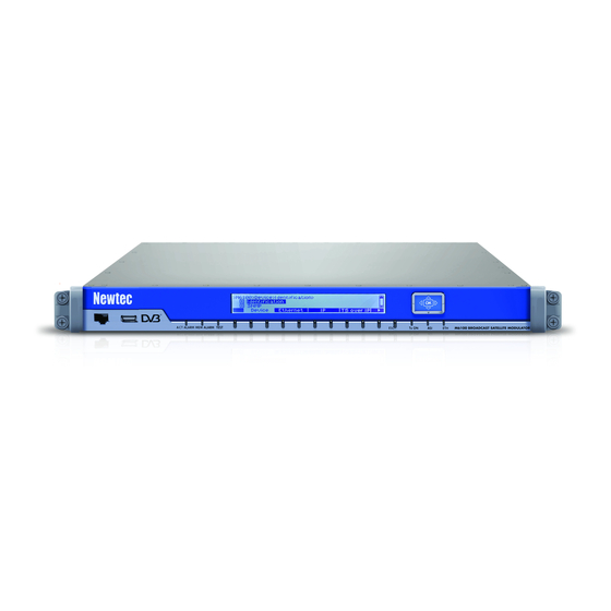
M6100 Broadcast Satellite Modulator Physical Description 7 Physical Description 7.1 Front Panel Description The device can be configured, controlled and monitored using the front panel. The front panel consists out of the following parts. For more information please refer to section: How to Use the Front Panel. on page 53... -
Page 25: Soft Buttons And Navigation Buttons
7.1.3 Front Panel Management Interface The management interface allows the system administrators to manage the M6100 Boadcast Satellite Modulator and monitor its operation. Note that this interface is disabled by default. -
Page 26: Usb Interface
M6100 Broadcast Satellite Modulator Physical Description 7.1.4 USB Interface The USB interface is a flash drive connector that can be used to perform a license or software upgrade. 7.1.5 LED Status Indicators The following table describes the LED indicators. LED Color Description A general device or interface alarm is present on the device. -
Page 27: Back Panel Description
Physical Description 7.2 Back Panel Description The following figure shows the possible connections on the M6100. The back panel connections available depend on the specific hardware configuration of your device. The maximum force that may be used to fix the SMA (L-Band monitor OUT) connector is restricted to 1.2Nm! - Page 28 M6100 Broadcast Satellite Modulator Physical Description Hardware configuration option with ASI inputs and outputs (Ordering number CH-01 and AS-02) The 10MHz REF out is optional and is selected during ordering. (Ordering number is RO-01.) Newtec Proprietary V1.4 Confidentiality: Unrestricted...
- Page 29 M6100 Broadcast Satellite Modulator Physical Description Hardware configuration option with DC-BUC on L-Band TX (Ordering number OU-05 or OU-06) Newtec Proprietary V1.4 Confidentiality: Unrestricted...
-
Page 30: Power Connector
M6100 Broadcast Satellite Modulator Physical Description 7.2.1 Power Connector This connector has a protective earthing incorporated. Insert the mains plug only in a socket that has a protective earth contact. Any interruption of the protective conductor inside or outside the device causes hazards or electrical shocks. -
Page 31: Earth Ground
M6100 Broadcast Satellite Modulator Physical Description 7.2.2 Earth Ground On the rear panel of the equipment an earth ground is available. It is provided to: • Ensure that all equipment chassis fixed within a rack are at the same technical earth potential. -
Page 32: Craft Interface
Speed 115200 baud; • Eight data bits; • No parity bit; • One stop bit. Use the following pin connections to create a crossover cable between the M6100 Boadcast Satellite Modulator and the managing device. Name Function Not connected Rx-D Receive Data... -
Page 33: Alarm Interface
M6100 Broadcast Satellite Modulator Physical Description 7.2.4 Alarm Interface The alarm interface can be used to build up device redundancy switching systems. When using the AZ202 Universal Redundancy Switch it is not mandatory to use alarm contacts. The Universal Redundancy Switch can also gather the alarm status from the different pieces of equipment in the setup over the management interface. - Page 34 M6100 Broadcast Satellite Modulator Physical Description The following figure shows how to connect the alarm cables in a 1+1 redundancy system. Newtec Proprietary V1.4 Confidentiality: Unrestricted...
-
Page 35: Getting Started
» Press to confirm and save the setting; » Connect an Ethernet cable between the Mgmt1 port on the back panel of the M6100 and the management PC. (The state indication on the front panel is changed from off to on). -
Page 36: Set Date And Time
M6100 Broadcast Satellite Modulator Getting Started Make sure that the management PC has access to this IP address or it belongs to this IP range. If needed it is possible to configure the Mgmt Gateway. To configure the Mgmt Gateway »... -
Page 37: Configure And Save
M6100 Broadcast Satellite Modulator Getting Started 8.3 Configure and Save You can configure settings using the front panel, the graphical user interface (GUI) or the command line interface (CLI). Please save to fix your configured settings. To save settings via the front panel: »... -
Page 38: How To Manage The Device
In some cases, there is a difference between the location of a parameter in the GUI and a location via the front panel. The parameter location is displayed as follows: M6100 >> Branch >> Zero or more Sub Branches >> Leafs The previous line indicates the following: » Navigate to branch;... - Page 39 M6100 Broadcast Satellite Modulator How to Manage the Device For example: M6100 >> Device Setup >> Mgmt Interface >> IP >> Mgmt1 IP Address/Prefix The previous line indicates the following: » Select Mgmt Interface; » Navigate to IP Address; » Insert a new value for Mgmt1 IP Address/Prefix.
-
Page 40: Management Ethernet Interfaces
To enable link redundancy, refer to Ethernet Link Redundancy. on page 34 Statistics M6100 >> Device Setup >> Mgmt Interface >> Statistics This provides an overview of the amount of traffic that is passing over the different management Ethernet ports. The following statistics are displayed: •... -
Page 41: Management Ip Connectivity
Note: Before configuring the device make a proper design of the system setup. To configure the management IP Addresses of the device go to the following location: M6100 >> Device Setup >> Mgmt Interface >> IP Address • Mgmt Gateway: This is the access point for the management port of the device. -
Page 42: Ethernet Link Redundancy
M6100 Broadcast Satellite Modulator How to Manage the Device 9.4 Ethernet Link Redundancy It is possible to enable link redundancy (also known as bonding) on the management Ethernet interfaces. Link redundancy is used to eliminate downtime as much as possible in the system setup. This increases the reliability of the system. - Page 43 M6100 Broadcast Satellite Modulator How to Manage the Device M6100 >> Device Setup >> Mgmt Interface >> IP Address >> Link Redundancy When link redundancy is activated, the bond interface must be configured. This bond interface has an IP Address that is used as destination address by the source.
-
Page 44: How To Use The Graphical User Interface
M6100 Broadcast Satellite Modulator How to Manage the Device 9.5 How to Use the Graphical User Interface The graphical user interface is a web application that gives remote access to the M6100. It allows the user to: • Manage the device;... - Page 45 M6100 Broadcast Satellite Modulator How to Manage the Device Newtec Proprietary V1.4 Confidentiality: Unrestricted...
-
Page 46: User Profiles
M6100 Broadcast Satellite Modulator How to Manage the Device 9.5.2 User Profiles The three possible user profiles are described in the following sections. For security reasons it is recommended to change the default passwords of the user profiles. For more information please refer to section: Change a Password. on page 41... -
Page 47: Operator Profile
How to Manage the Device 9.5.2.2 Operator Profile Newtec recommends using this profile when configuring or maintaining a device. The operator profile is developed in such a way that the user is not overloaded with all possible parameters.This is done to keep the configuration and maintenance of the device light and easy. -
Page 48: Switch User Profile
M6100 Broadcast Satellite Modulator How to Manage the Device 9.5.3 Switch User Profile » Click logged in as guest/operator/expert (The User options window is displayed.) » Click Switch User to change the user profile. (The Login window is displayed.) The default User Name and password for the operator profile is as follows: –... -
Page 49: Change A Password
M6100 Broadcast Satellite Modulator How to Manage the Device 9.5.4 Change a Password » In the users options window click Change Password » Enter the Current Password and then the New Password. Also confirm the new password. » Click Change Password to confirm the New Password. -
Page 50: Gui Pane Description
The bottom left row of the banner is editable and can be used to assign a unique identifier to the device. Do this by clicking on the label. (In the previous figure, the label is marked: M6100). This name is also shown in the tab of the web browser and makes it easier to identify different devices. - Page 51 M6100 Broadcast Satellite Modulator How to Manage the Device Pane Pane name Function Alarms list The alarm list displays the alarms generated by the device. pane Alarms are sorted first by their activity and then by their severity (from critical alarms to warnings).
-
Page 52: Overview Tab
M6100 Broadcast Satellite Modulator How to Manage the Device 9.5.6 Overview Tab The Overview tab contains a schematic representation of the data flow in the device. The signal passes different functional blocks and each block contains a function name, basic settings and counters. - Page 53 M6100 Broadcast Satellite Modulator How to Manage the Device Functional Blocks Description Device Management Functional block that allows to manage, configure and monitor the device management parameters. For Example: • Configure the management interfaces; • Manage the interface link redundancy;...
-
Page 54: Detailed View Of A Functional Block
M6100 Broadcast Satellite Modulator How to Manage the Device 9.5.7 Detailed View of a Functional Block Click on the enlarge button in the top right corner of a functional block to view more parameters for the functional block. Refer to the following figure: Newtec Proprietary V1.4... -
Page 55: Tree View
M6100 Broadcast Satellite Modulator How to Manage the Device 9.5.8 Tree View The tree view shows all device parameters arranged in a tree structure consisting of branches, sub branches and leaves. The following pane is displayed: The tree view, divides the function controls pane in to two extra panes, they are called A and B in the previous figure: The following table describes the extra panes of the tree view. -
Page 56: Alarms Pane
M6100 Broadcast Satellite Modulator How to Manage the Device 9.5.9 Alarms Pane The Alarms pane shows the alarms generated by the device. Alarms are sorted first by their activity and then by their severity (from critical alarms to warnings.) The alarm list pane contains the following information:... -
Page 57: Status Bar
M6100 Broadcast Satellite Modulator How to Manage the Device 9.5.10 Status Bar The status bar informs on the following: Cfg saved is red when the active configuration is modified but not saved. To save the configuration, refer to section: Save a Configuration on page 84 The following table describes the available LEDs. -
Page 58: Colors Used In The Gui
M6100 Broadcast Satellite Modulator How to Manage the Device 9.5.11 Colors Used in the GUI In the schematic overview, colors are used per functional block to provide the status of the device. The traffic flow is also indicated between the functional blocks by arrows. -
Page 59: Parameters In The Gui
M6100 Broadcast Satellite Modulator How to Manage the Device 9.5.12 Parameters in the GUI The GUI contains different types of parameter dialogue boxes to configure all parameters. Dialogue box Example Type Drop-down-list-box Edit This pencil icon indicates that it is possible to edit the parameter Lock The lock icon indicates that it is not possible to edit the parameter. -
Page 60: Invalid Values
M6100 Broadcast Satellite Modulator How to Manage the Device Show All Click this dialog box to open the functional block. Open Detailed View Click this icon to open the detailed view, zooming in on the parameters of the specific block. -
Page 61: How To Use The Front Panel
M6100 Broadcast Satellite Modulator How to Manage the Device 9.6 How to Use the Front Panel This section explains how the devices can be configured using the front panel. The following figure shows the navigation buttons, indicators and connectors to the front panel. -
Page 62: Front Panel Buttons Description
M6100 Broadcast Satellite Modulator How to Manage the Device 9.6.2 Front Panel Buttons Description The following figure displays the different control buttons of the front panel. The following table describes the buttons displayed in the previous figure. Name/Symbol Description Arrow UP Navigate to the upper item. -
Page 63: Root Menu Pane
M6100 Broadcast Satellite Modulator How to Manage the Device 9.6.3 Root Menu Pane This pane represents a list of the available branches. It is presented at the bottom of the display in a horizontal way. For example the following main menus: •... -
Page 64: Tree Menu Pane
M6100 Broadcast Satellite Modulator How to Manage the Device 9.6.4 Tree Menu Pane • The first row of the tree menu indicates the current location in the device. For example: M6100 > Device> Identification • A selectable item in the tree menu pane is visualized with a dark background. -
Page 65: Example: Change The Access Level
M6100 Broadcast Satellite Modulator How to Manage the Device 9.6.5 Example: Change the Access Level Change the access level/user profile in the front panel. Proceed as follows: » Select Device using the corresponding Soft button » Navigate to Frontpanel » Click (to unfold the branch) »... -
Page 66: Example: Set The Output Frequency
M6100 Broadcast Satellite Modulator How to Manage the Device 9.6.6 Example: Set the Output Frequency » Select Modulator using the corresponding Soft Button; » Navigate to Output Frequency; » Click New value is displayed, indicating the current position by a blinking number. -
Page 67: Command Line Interface (Cli)
» Configure the IP Address of the management interface using the front panel. Make sure that the IP address of the M6100 Boadcast Satellite Modulator is in the same range as the IP Address of the managing device or that a default gateway is configured. - Page 68 Speed 115200 baud; • Eight data bits; • No parity bit; • One stop bit. » Make an connection between the managing device and the M6100 Boadcast Satellite Modulator. For more information please refer to section: Craft Interface on page 24 Newtec Proprietary V1.4 Confidentiality: Unrestricted...
-
Page 69: Open The Cli Using A Terminal Emulator
M6100 Broadcast Satellite Modulator How to Manage the Device 9.7.2 Open the CLI using a Terminal Emulator A terminal emulator is an application that can act as a client for the SSH (Secure Shell) computing protocol and as a serial console client. In this user manual PuTTY is used as terminal emulator. Go... -
Page 70: Log In As Expert
M6100 Broadcast Satellite Modulator How to Manage the Device 9.7.3 Log In as Expert The CLI interface can only be accessed by the expert user. » To login as expert type the following: » login as: expert » password: expertexpert »... - Page 71 M6100 Broadcast Satellite Modulator How to Manage the Device configuration/ reset* softwareupgrade* license/ [M6100] modulator# show transmitctrl/ externalconvertor/ dvbcid/ equalink/ dvbs2/ mode Dvbs2 transmit outputfrequency 1550.000000 MHz outputband lBand ..Newtec Proprietary V1.4 Confidentiality: Unrestricted...
-
Page 72: Help
M6100 Broadcast Satellite Modulator How to Manage the Device 9.7.4.2 Help The help command is used to provide information on a command or parameter. Always type help at the end. For example: [M6100] device # reset help reset the device... -
Page 73: Navigate Through The Branches Of The Device
M6100 Broadcast Satellite Modulator How to Manage the Device 9.7.5 Navigate Through the Branches of the Device Use the following commands to navigate through the different branches of the device. In this manual the commands are presented as follows: The input message is displayed as follows:... -
Page 74: Return To The Main Branch
M6100 Broadcast Satellite Modulator How to Manage the Device 9.7.8 Return to the Main Branch » Type one of the following commands: ] (key combination) exitall CTRL-Z For Example: [M6100] modulator dvbs2# exitall [M6100]# [polaris] modulator dvbs2# / [M6100]# [M6100] modulator dvbs2# [CTRL-Z]... -
Page 75: Supported Key Presses In The Cli
M6100 Broadcast Satellite Modulator How to Manage the Device 9.7.9 Supported Key Presses in the CLI The CLI supports the following input characters: Directly from the keyboard • All printable characters; • Delete; • Arrows; • Tab: used to perform command completion;... - Page 76 M6100 Broadcast Satellite Modulator How to Manage the Device Key Combinations Key Combination Description CTRL+A Go to beginning of the line. CTRL+B Move the cursor backwards. CTRL+C Flush the current line ignoring the contents and start a new line. CTRL+D Delete to the right.
-
Page 77: Displayed Units
M6100 Broadcast Satellite Modulator How to Manage the Device 9.7.10 Displayed Units Some variables are by default scaled to a more readable unit. For example: • Symbol rate in Mbaud; • Bit rate in Mbps; • Frequencies in MHz. When entering a new value (without specifying a scale) the default unit scaling is applied. - Page 78 M6100 Broadcast Satellite Modulator How to Manage the Device For example: [M6100] # device identification label get Modulator It is also possible to navigate to the parameter location and make a request. [M6100] # mgmtintf [M6100] mgmtintf # mgmtgateway get 192.168.254.206...
-
Page 79: Dynamic Tables
How to Manage the Device 9.7.12 Dynamic Tables The data model of the M6100 Boadcast Satellite Modulator uses a lot of tables. These tables are used to keep related information together. The CLI allows to display these tables. Furthermore it is possible to access and change values of a parameter in a specific row and column, this makes the tables dynamic. -
Page 80: Add A New Row To A Table
M6100 Broadcast Satellite Modulator How to Manage the Device M6100 datainterface link# data2 set enable=on 9.7.12.3 Add a New Row to a Table In case of empty tables, the command showtable only shows the column headers. This indicates the different parameters that can be defined for a row in this table. -
Page 81: Delete A Row From A Table
M6100 Broadcast Satellite Modulator How to Manage the Device 9.7.12.4 Delete a Row from a Table Use the command "delete " to remove a row from the table. For Example: M6100 gsedecapsulation channels# delete senegal Newtec Proprietary V1.4 Confidentiality: Unrestricted... -
Page 82: Snmp
SNMPv2c is used in the device. The MIBs as supported by the device can be downloaded from the GUI Device Tasks Pane. M6100 >> Device Setup >> Access Control >> SNMP SNMP (Simple Network Management Protocol) is used when the customer wants to control the device (or a complete system) through a NMS (Network Management System). -
Page 83: Consult Or Download The Snmp Mibs (Management Information Base)
M6100 Broadcast Satellite Modulator How to Manage the Device 9.8.1 Consult or Download the SNMP MIBs (Management Information Base) The SNMP MIBs can be downloaded using the GUI interface. » Navigate to the Tasks Pane (GUI); » Click Documentation; » Click SNMP MIBs. -
Page 84: File Transfer Protocol (Ftp)
Enable or disable the FTP (File Transfer Protocol) server service and the FTP account on following location: M6100 >> Device >> FTP The FTP service (anonymous account) is activated by default. For security reasons, it is advised to disable the anonymous ftp-account. - Page 85 M6100 Broadcast Satellite Modulator How to Manage the Device For example: Newtec Proprietary V1.4 Confidentiality: Unrestricted...
-
Page 86: General Device Settings And Actions
By default SNMP, CLI and FTP are enabled. Login as expert user and navigate to the following locations to enable or disable these settings. M6100 >> Device >> SNMP M6100 >> Device >> CLI M6100 >> Device >> FTP M6100 >>... -
Page 87: License File
M6100 Broadcast Satellite Modulator General Device Settings and Actions 10.2 License File A license file contains the information about all the features/options that are enabled or disabled on the device. A license file is device dependent. When the license file is not valid, the device has limited functions. - Page 88 M6100 Broadcast Satellite Modulator General Device Settings and Actions » Select License Upgrade; » Browse to the folder where the new license.ini file is stored; » Select the licence.ini file and Click Open; The following message is displayed: Importing / upgrading a licence file reboots the device! »...
-
Page 89: Configuration Settings
M6100 Broadcast Satellite Modulator General Device Settings and Actions 10.3 Configuration Settings » Log in as Operator or Expert (Refer to section: Switch User Profile on page 40 » Navigate to the Tasks Pane » Click Device; » Click Configurations; From this menu it is possible to manage the configurations of the device. -
Page 90: Configuration File
M6100 Broadcast Satellite Modulator General Device Settings and Actions 10.3.1 Configuration File There are two kinds of configuration sets stored on the device: • Configuration files with device specific parameters; • Configuration files with application specific parameters. Device Specific Parameters These parameters are used to set up device specific settings and they are excluded from the imported/exported configuration files. -
Page 91: Active Configuration
M6100 Broadcast Satellite Modulator General Device Settings and Actions 10.3.2 Active Configuration The active configuration is the configuration that is currently used on the device. The active configuration is not necessarily a configuration that is saved on the device. When a configuration is completed, it is recommended to save this configuration onto the device. -
Page 92: Save A Configuration
M6100 Broadcast Satellite Modulator General Device Settings and Actions 10.3.4 Save a Configuration When parameters are changed, they are not directly saved into the active configuration. » Navigate to the Tasks Pane to check the available configurations; » Click Device;... -
Page 93: Load A Configuration
M6100 Broadcast Satellite Modulator General Device Settings and Actions Note: If the BISS setupID of the device is not the same as the BISS setupID of the device having generated the configuration, the copy will result in corrupted BISS parameters. (Refer to section: Basic Interoperable Scrambling System (BISS) on page 192... -
Page 94: Export A Configuration
M6100 Broadcast Satellite Modulator General Device Settings and Actions 10.3.7 Export a Configuration Use this to export a configuration file. Depending on the management interface GUI or CLI the following is done: – GUI: the file is downloaded by the browser;... -
Page 95: Delete A Configuration
M6100 Broadcast Satellite Modulator General Device Settings and Actions 10.3.8 Delete a Configuration Delete a configuration file from the device when it becomes obsolete. » Navigate to the Tasks Pane; » Click Device; » Click Configurations; » Click the Config Name you want delete;... -
Page 96: Make A Configuration File Bootable
M6100 Broadcast Satellite Modulator General Device Settings and Actions 10.3.9 Make a Configuration File Bootable » Navigate to the Tasks Pane; » Click Device; » Click Configurations; » Click the following icon » Click the Config Name you want make the boot configuration;... -
Page 97: Software Upgrade
M6100 Broadcast Satellite Modulator General Device Settings and Actions 10.4 Software Upgrade A software upgrade is needed in two cases: • To provide bug fixes and/or software enhancements; • To activate a new functionality in the device. The upgrade procedure is explained on the next page. - Page 98 M6100 Broadcast Satellite Modulator General Device Settings and Actions » Select the file and click Open. The following message is displayed: Software Upgrade: This operation will reboot your device! Are you sure, you want to upgrade the device firmware with the content of "installer.bin"?
-
Page 99: Device Identification
– Software Version; – Device options (displays the sales code and the code description) This displays the current options of the device. 10.6 Logging M6100 >Device Setup >> Logging Enable or disable logging. Logging can be performed on the following levels: •... -
Page 100: Syslog Filter
M6100 Broadcast Satellite Modulator General Device Settings and Actions 10.6.1 Syslog Filter It is possible to assign up to nine different log levels to the following facilities. Facility Log Description Alarms An alarm is detected on the device. Configuration Configuration changes on the device. -
Page 101: Export Or Clear Logging
M6100 Broadcast Satellite Modulator General Device Settings and Actions 10.6.2 Export or Clear Logging » Navigate to the Tasks Pane; » Click Logs; » Click Device Log. Use this menu to View Download the local board logging. • When a view is requested, the log file is opened in a separate browser. -
Page 102: Interpretation Of A Device Log File
M6100 Broadcast Satellite Modulator General Device Settings and Actions 10.6.3 Interpretation of a Device Log File A standard log file looks as follows: [configuration-INFO][2012-12-16 10:27:53] writeValue /Root/SystemAlarm/Log/Source=GeneralInterface [alarms-INFO][2012-12-16 10:27:54] alarm General Interface: OFF Facility Log Level Time Extra information about... - Page 103 M6100 Broadcast Satellite Modulator General Device Settings and Actions Newtec Proprietary V1.4 Confidentiality: Unrestricted...
-
Page 104: Date And Time
Universal Time). Enter the different NTP peer IP Addresses to which must be synchronized. The M6100 Boadcast Satellite Modulator acts as a client and periodically queries the server for a precise UTC time reference. It is possible to enter up to four NTP peer IP addresses. - Page 105 M6100 Broadcast Satellite Modulator General Device Settings and Actions When the NTP peer addresses are inserted, time and date of the M6100 are updated with the received information as soon as the M6100 can connect to one of the NTP peer servers.
-
Page 106: Device Monitoring
M6100 Broadcast Satellite Modulator General Device Settings and Actions 10.9 Device Monitoring M6100 >> Device Setup >>Monitor The following device level parameters are monitored. • Temperature; • Board Power supply; • CPU (Central Processor Unit) load; • Memory usage; •... -
Page 107: Reset The Device
M6100 Broadcast Satellite Modulator General Device Settings and Actions 10.10 Reset the Device Resetting the device causes data loss on an active link! When a user wants to perform a reset using the front panel or CLI, no caution message is displayed! The device can be reset when needed. -
Page 108: Alarm Handling
(hide) alarms; • assign alarms to a general interface or general device alarm. Navigate to the following location to perform alarm handling. M6100 >> Device Setup >Alarm Handling List of Alarms For a comprehensive list of alarms, refer to Appendix A - Alarm List on page 210... -
Page 109: Alarm Masking
You can mask individually selected alarms. This means that you can hide alarms. Be careful when configuring this, as a masked alarm is not recognized anymore by the M6100. Alarm masking can also impact device redundancy, this because the alarm is not propagated into a general device or a general interface alarm. - Page 110 M6100 Broadcast Satellite Modulator General Device Settings and Actions Eth Data2 Link Failure: Alarm Mask = On 1. No active alarms are present; 2. The Ethernet cable of Eth Data2 is removed; 3. The "Eth Data2 Link Failure" alarm is masked so no alarms are triggered! Newtec Proprietary V1.4...
-
Page 111: Alarm Configuration
For example, the "Temperature alarm", by default generates a general device alarm. The general device alarm switches off the main functional blocks of the M6100, to reduce the CPU load of the device. - Page 112 M6100 Broadcast Satellite Modulator General Device Settings and Actions We want that the "Eth. Mgmt Itf Link Failure" alarm triggers a General Interface Alarm. (The reason could be that this alarm must trigger a switchover to a redundant device). Note that a "Mgmt Itf Failure" by default does not trigger the alarm switches. To change this behavior you have to assign the "Mgmt Itf Failure"...
- Page 113 M6100 Broadcast Satellite Modulator General Device Settings and Actions Newtec Proprietary V1.4 Confidentiality: Unrestricted...
-
Page 114: Clear Alarm Counters
M6100 Broadcast Satellite Modulator General Device Settings and Actions 10.11.3 Clear Alarm Counters Alarm counters as presented in the of the GUI and can be cleared all at Alarms Pane on page 48 once. 10.12 Reference Clock M6100 >> Ref Clock Configure the reference clock. -
Page 115: Device Redundancy
General Device Settings and Actions 10.13 Device Redundancy Redundancy is very important as a single failure of the M6100 affects many services at the same time. Reliable operation of the M6100 in a satellite network is of key importance. The M6100 works seamlessly together with the Newtec AZ202/AZ212 redundancy switches to provide best-in-class system uptime. - Page 116 M6100 Broadcast Satellite Modulator General Device Settings and Actions To Enable or Disable device redundancy go to the following location: M6100 >> Device >> Redundancy By default, device redundancy is disabled. Initial Redundancy State: • Standby (default value): This means when the device starts up and redundancy is enabled, the initial state of the redundancy is standby.
-
Page 117: Data Interfaces
Data Interfaces 11 Data Interfaces 11.1 Data Ethernet Interfaces The data interfaces can be configured on the following location: M6100 >> Data Interface >> Ethernet • Data1 (This port is the top port on the back panel indicated as data1); •... -
Page 118: Data Ip Connectivity
The following figure is an example of a setup: Use a network drawing to define the data input interfaces: Make sure that the source device and the M6100 belong to the same IP range or the content is routed to the correct Data IP address. -
Page 119: Virtual Ip Address
M6100 Broadcast Satellite Modulator Data Interfaces 11.2.1 Virtual IP Address Use virtual IP Addresses when working with device redundancy and a USS (Newtec's Universal Switching System). The virtual IP Addresses are configured on the main device. These are automatically synchronized to the stand-by (spare) device. -
Page 120: Data Ethernet Link Redundancy
When the link state of the active interface goes down (physically broken connection), the other interface takes over the operation. Refer to the following figure: M6100 >> Data Interface >> Link Redundancy Newtec Proprietary V1.4... - Page 121 M6100 Broadcast Satellite Modulator Data Interfaces Options Descriptions Data1 or Data2 (Data) The bonding interface is active. There is no preference in priority between the two available interfaces. Data1 before Data2 (Data) The bonding interface is active. Interface Data1 has priority over interface Data2. This means that when Data1 is available, this will be the active interface.
-
Page 122: Asi Input
M6100 Broadcast Satellite Modulator Data Interfaces 11.4 ASI Input Configure the ASI input interfaces on following location. M6100 >> ASI Input >> Input Selection The two ASI inputs make it possible to create a link redundant interface input. Selection Description None The ASI input is disabled and incoming traffic is discarded. -
Page 123: Input Framing
When a passive splitter is used and this compensation is not enabled, the incoming signal might be degraded too much so that a correct modulation cannot be guaranteed. 11.4.2 Input Framing Configure the input framing type. M6100> ASI Input > Input Framing The incoming packets can be: • TS188 (transport stream with 188-byte packets);... - Page 124 M6100 Broadcast Satellite Modulator Data Interfaces Depending on the hardware version of the device the back panel has four or six ASI interfaces available. This is also reflected in the output selection parameters. The following sections shows the behavior in case of a back panel with four ASI and six ASI interfaces.
- Page 125 M6100 Broadcast Satellite Modulator Data Interfaces Newtec Proprietary V1.4 Confidentiality: Unrestricted...
- Page 126 M6100 Broadcast Satellite Modulator Data Interfaces Six ASI interfaces available on the back panel (from R1.4 onwards) The following figures show different possibilities of output selection and to which output interface the signal is forwarded. (see next page) Newtec Proprietary V1.4...
- Page 127 M6100 Broadcast Satellite Modulator Data Interfaces PRBS can be activated from the following locations: M6100 >> ASI Input M6100 >> ASI Output Also refer to section: PRBS Generator on page 174 Newtec Proprietary V1.4 Confidentiality: Unrestricted...
-
Page 128: Ts Over Ip
M6100 Broadcast Satellite Modulator Data Interfaces 11.6 TS over IP 11.6.1 Why TS over IP Transport stream over IP is a solution that is introduced to reduce costs and create more flexibility for teleports and network operators. Using Ethernet interfaces provides the flexibility of sending media files over the Internet towards the modulator. -
Page 129: Ts Over Ip Settings
M6100 Broadcast Satellite Modulator Data Interfaces 11.6.4 TS over IP Settings The incoming traffic on the Ethernet interface of the modulator are IP packets with Transport Streams included. The IP information must be removed to recover the original transport stream. Do... -
Page 130: Ts Over Ip Input Interface
Data Interfaces 11.6.5 TS over IP Input Interface Configure the TsoIP input interface. M6100> TS over IP >> Input Interface The two data Ethernet inputs make it possible to create a redundant interface input. For more information pleaser refer to Data Ethernet Link Redundancy. on page 112... -
Page 131: Ts Encapsulation Protocol
M6100 Broadcast Satellite Modulator Data Interfaces 11.6.6 TS Encapsulation Protocol M6100> TS over IP >> TS Encap Protocol To transport these time critical media files over IP networks it is possible one of the following protocols can be used. •... -
Page 132: Rtp
M6100 Broadcast Satellite Modulator Data Interfaces 11.6.6.2 RTP The Real-time Transport Protocol is used to send MPEG Transport Stream packets from a source (encoder) to the modulator over an IP network. This protocol is based on UDP but it uses extra header information such as sequence numbers and timestamps. -
Page 133: Rtp Fec
TS is inserted periodically in a parallel UDP port. This mechanism is standardized by SMPTE.org in the standards SMPTE 2022 of which the M6100 Broadcast Satellite Modulator supports SMPTE 2022-1 and SMPTE 2022-2. These standards support only the protection of CBR (Constant Bit Rate) TS streams. - Page 134 M6100 Broadcast Satellite Modulator Data Interfaces • L = the period or space between the non-consecutive packets or the amount of columns in the matrix; • D = defines the amount of rows in the matrix. When the transport streams are aligned in the matrix the XOR function is applied to compute the FEC packets per column and row.
- Page 135 M6100 Broadcast Satellite Modulator Data Interfaces The M6100 Broadcast Satellite Modulator has all hardware on board to support L(column) and D (Row FEC) up to 20 where L*D<=100. The M6100 Broadcast Satellite Modulator is able to detect the FEC packets automatically. These FEC packets are used to reconstruct the original transmitted transport stream.
-
Page 136: Ip Address Type
IGMPv2 and IGMPv3 (standards) are supported by the M6100 Satellite Broadcast Modulator. 11.6.7 Traffic Profile In the M6100 Broadcast Satellite Modulator the traffic profile must comply with the profile used in the encoder/video multiplexer. This is needed to ensure that the M6100 Broadcast Satellite Modulator recognizes the traffic. -
Page 137: Cbr (Constant Bit Rate)
This means when too much packets are received data is discarded. 11.6.7.2 CBR (Constant Bit Rate) M6100> TS over IP >> Traffic Profile This is the property of a transport stream where the packet rate is constant over time, in other words there are always the same number of packets in two time intervals of the same duration. -
Page 138: Maximum Traffic Jitter And Buffer Delay
(First In First Out). The rate is set by the Input TS Bit Rate (M6100 >> TS over IP >> Input TS Bit Rate) parameter. Any high frequency jitter is removed this way. - Page 139 M6100 Broadcast Satellite Modulator Data Interfaces The Buffer Delay equals Max Traffic Jitter + 200ms if not limited by the Max Buffer Delay value. In case the reference clocks of TS encoder and modulator are the same, the buffer will cope with up to 500 ms traffic jitter when Max Traffic Jitter is set at 300...
-
Page 140: Input Ts Bit Rate
Data Interfaces 11.6.9 Input TS Bit Rate M6100 TS over IP >> Input TS Bit Rate Define the input TS bit rate when the CBR traffic profile is selected. With the rate adapter enabled, the output rate will be adjusted to match the Modulator symbol rate. -
Page 141: Multiprotocol Encapsulation
M6100 Broadcast Satellite Modulator Data Interfaces M6100>TS over IP >> Monitor >> Source Info This monitoring parameter provides the actual used input source IP Address and UDP port. Source redundancy is only applicable for those remote devices sending to the same multicast address and same UDP port.Thus, source redundancy cannot be used for... - Page 142 M6100 Broadcast Satellite Modulator Data Interfaces M6100>MPE >> Enable MPE Using MPE makes it possible to transmit data along with the video transport stream. This data can contain for example: software image files for DTH set-top boxes,Multi Home Platform information or general low bit rate data for distribution in private networks.
-
Page 143: Mpe Input Selection
M6100 Broadcast Satellite Modulator Data Interfaces 11.7.1 MPE Input Selection M6100>MPE >> Input Selection Configure the MPE input interface. The two data Ethernet inputs make it possible to create a redundant interface input. Refer to section: Data Ethernet Link Redundancy. on page 112 Selection Description None No input selection, the functional block is not active. -
Page 144: Packet Id
M6100 Broadcast Satellite Modulator Data Interfaces 11.7.2 Packet ID M6100> MPE >> PID When MPE is enabled, it is needed to add a packet Identifier to this stream. This makes it possible to filter the correct data on the receiving end. -
Page 145: Program-Specific Information (Psi-Si) Insertion
M6100 Broadcast Satellite Modulator Data Interfaces 11.7.3 Program-Specific Information (PSI-SI) Insertion M6100>MPE >> PSI-SI Insertion The program specific information is metadata about a program and is part of the MPEG TS. The receiver uses the program-specific information to identify the properties of the stream. - Page 146 M6100 Broadcast Satellite Modulator Data Interfaces The following additional information can be added: • Program Number; • Program Map Table – PMT PID When no signaling is present in the received TS, use the following settings to insert signaling when applicable.
-
Page 147: Traffic Classification, Shaping And Channels
M6100 Broadcast Satellite Modulator Data Interfaces 11.7.4 Traffic Classification, Shaping and Channels M6100>MPE >> Traffic Classification The purpose of this block is to classify, shape and send out the data to the correct output channel. The following figure represents the different steps that are performed: Newtec Proprietary V1.4... -
Page 148: Traffic Classification
M6100 Broadcast Satellite Modulator Data Interfaces 11.7.4.1 Traffic Classification The purpose of traffic classification is to identify flows/streams of traffic that need a different treatment. Traffic classification is based on the destination Network Address, via classification expressions or a combination of both. - Page 149 M6100 Broadcast Satellite Modulator Data Interfaces Parameter Description Classification Enter a logical classification name/rule. Name Enable Activate the classification rule. Classification It is possible to define an expression to classify/filter out specific traffic. This Expression expression can be standalone or combined with the Network Address (see previous parameter).
-
Page 150: Traffic Shaping
M6100 Broadcast Satellite Modulator Data Interfaces 11.7.4.2 Traffic Shaping The following figure illustrates how the classified traffic is shaped by the traffic shaper. Per classified traffic node, traffic shaping can be performed. Traffic shaping makes it possible to restrict the maximum given PIR (Peak Information Rate) in a flexible way. - Page 151 M6100 Broadcast Satellite Modulator Data Interfaces This is used to ensure that the available data rate is distributed in the most appropriate manner among the users of the satellite network. The traffic shaper provides adaptive traffic shaping, which makes it easy for shaping the traffic of networks where the throughput of the link is varying over time.
-
Page 152: Channels
M6100 Broadcast Satellite Modulator Data Interfaces 11.7.4.3 Channels Channels are logical pipes that are used to transport shaped traffic. A channel can be used to transport a certain service towards a terminal or a group of terminals. A terminal (receiving device) can receive multiple channels (for example: different services). - Page 153 M6100 Broadcast Satellite Modulator Data Interfaces Parameter Description Channel Name Enter a logical channel name, for example the service that is transported over this channel (For example: VoIP Traffic, ) Enable This must be Enabled (On) otherwise the channel is not recognized and the data cannot be encapsulated.
-
Page 154: Bbf Over Ip In
– Data Bond (this is the bond interface, both physical interfaces and link redundancy must be activated). • Reset monitoring counters. The following figure shows an example of a setup between the AZ810 and the M6100. Newtec Proprietary V1.4 Confidentiality: Unrestricted... - Page 155 M6100 Broadcast Satellite Modulator Data Interfaces BBF Stream Description Configuration Name Enter a logical name. Enable Enable the specified BBF endpoint. IP Address Unicast: Type Multicast: Multicast IP Define to what multicast group the device belongs. Address UDP Port Define on what UDP port the BBFs are received.
- Page 156 M6100 Broadcast Satellite Modulator Data Interfaces Monitoring Description Parameter Input Bit Rate The incoming bit rate in Mbps measured per stream. Source Info This monitoring parameter provides the actual used input source IP Address and UDP port. Input Counter Displays the amount of incoming BBFs.
-
Page 157: Features Descriptions
M6100 Broadcast Satellite Modulator Features Descriptions 12 Features Descriptions 12.1 Modulator The modulator functional block is used to perform the actual modulation of the TS. M6100> Modulator The main parameters are: • Mode DVB-S/DVB-S2/S2-Extensions; • Transmit On/Off; • Output Level;... -
Page 158: Input Type
It reflects the alarm state's that are configured under transmit control. 12.1.4 Output Frequency and Output Band M6100 >> Modulator >> Output Frequency Set the output frequency of the modulator. The output frequency must be in-line with the device capabilities (L-band or IF band) and the system requirements. -
Page 159: Roll Off Factor And Occupied Bandwidth
M6100 Broadcast Satellite Modulator Features Descriptions 12.1.5 Roll Off Factor and Occupied Bandwidth M6100 >> >> Roll-Off Select the appropriate roll off factor. The possibilities are: • 35%; • 25%; • 20%; • 15% (Clean Channel Technology™); • 10% (Clean Channel Technology™);... - Page 160 M6100 Broadcast Satellite Modulator Features Descriptions Multicarrier: Occupied bandwidth = Symbol Rate*(1+Roll-Off factor). Example for Occupied bandwidth 3MHz. • DVB-S (35%) 2.2 Mbaud • DVB-S2 (15%) 2.6 Mbaud • DVB-S2 (25%) 2.4 Mbaud • DVB-S2 (10%) 2.7 Mbaud • DVB-S2 (20%) 2.5 Mbaud...
-
Page 161: Spectrum Polarity
M6100 Broadcast Satellite Modulator Features Descriptions 12.1.6 Spectrum Polarity M6100 >> Modulator >> Spectrum Polarity Spectrum inversion can be enabled in case an inverting upconverter is used. As a general rule transmissions on satellite need to be non-inverted. Most modern demodulators can detect and automatically adapt the spectrum inversion. - Page 162 M6100 Broadcast Satellite Modulator Features Descriptions The pure carrier is used during line-up and to perform cross polarization tests with the satellite operator. The test modulation settings are used for calibration and/or verification of the spectrum polarity. In this case, a carrier is modulated by a rotating vector with a period of baudrate/n. This results in a single spectral line at: +clock/n offset from the pure carrier.
-
Page 163: Amplitude Slope Equaliser
Features Descriptions 12.1.9 Amplitude Slope Equaliser M6100 >> Modulator >> Ampl Slope Equalizer Configure the amplitude slope equalizer. An amplitude slope in the up-converter or in the high power amplifier can be compensated by using this equalizer. The equalizer has a maximum range of ±... -
Page 164: Transmit Control
M6100 Broadcast Satellite Modulator Features Descriptions 12.1.13 Transmit Control M6100 >> Modulator >> Transmit Ctrl The transmission control parameters allows you to alter the default behavior of the transmitter. 12.1.14 External Convertor Navigate to enable the use of an external convertor (For example a Block Up Converter BUC). -
Page 165: Dvb-S Specific Settings
M6100 Broadcast Satellite Modulator Features Descriptions Direct Spectrum RF Frequency = LO Frequency + Output Frequency Inverted Spectrum RF Frequency = LO Frequency - Output Frequency 12.1.15 DVB-S Specific Settings 12.1.15.1 Modulation and Coding Define the ModCod that can be used. -
Page 166: Modulation And Coding
12.1.16.2 Modulation and Coding Define the ModCod that can be used. Newtec provides a tool (the DVB-S2 calculator) which calculates, in function of the chosen ModCod and other system parameters, the required Es/N0 for your application. All available ModCods are listed in: DVB-S2 on page 217... -
Page 167: Physical Layer Scrambling
M6100 Broadcast Satellite Modulator Features Descriptions When are Pilots Used in DVB-S2? In general it is advised to use pilots(especially in the following cases). • When a noticeable amount of phase noise is present (for example LNBs with "bad" phase noise);... -
Page 168: Dummy Pl Scrambler Mode
This Continuous mode is only valid for the dummy physical layer frames! The Continuous mode is not DVB compliant. As a consequence it is possible that some non-Newtec demodulators are not capable of working with this mode. 12.1.16.4.2 Physical Layer Scrambler Signature M6100 >>... -
Page 169: Roll Off Signaling
M6100 Broadcast Satellite Modulator Features Descriptions 12.1.16.4.3 Roll Off Signaling M6100 >> Modulator >> Roll Off Signaling • standard : (2 bits : "10") roll off signaling value is used for roll off = 20%; • reserved : (2 bits: "11") roll-off signaling value is "reserved" (11) is used for roll off < 20%. -
Page 170: Clock Output
For the reference clock settings and characteristics, refer to Reference Clock. on page 106 12.1.16.6 Roll Off Signaling M6100 >> Modulator >> Roll Off Signaling • standard : (2 bits : "10") roll off signaling value is used for roll off = 20%; •... -
Page 171: Reference Clock
M6100 Broadcast Satellite Modulator Features Descriptions 12.2 Reference Clock M6100 >> Ref Clock Configure the reference clock. This reference signal for an outdoor BUC can be multiplexed on the L-band Tx interface. A reference clock can be generated internally (default) or slave on an external source. -
Page 172: Ts Mux
ID into the Network Information Table (NIT). For more information please refer to section: NIT Carrier Identification. on page 166 12.3.1 Insert Signaling M6100 Boadcast Satellite Modulator> TS MUX >> PSI-SI Insertion Insert the Original Network Id (for SDT) as specified by the parameters Transport Stream Id and Network Id. - Page 173 M6100 Broadcast Satellite Modulator Features Descriptions The following figure shows the rate adapter functionality. Newtec Proprietary V1.4 Confidentiality: Unrestricted...
-
Page 174: Nit Carrier Identification
Features Descriptions 12.5 NIT Carrier Identification M6100 Boadcast Satellite Modulator> TS MUX >> NIT Carrier ID The carrier identification is used to reduce RFI (Radio Frequency Interference). The NIT carrier ID allows the satellite operators to identify and contact the source of interference quickly. The carrier ID is implemented in the Network Information Table (NIT) of the TS, more specifically into the network descriptors set of the NIT. -
Page 175: Dvb Carrier Identification
Features Descriptions 12.6 DVB Carrier Identification M6100 >> Modulator >> DVB Carrier Identification The DVB carrier identification standard is used to reduce RFI (Radio Frequency Interference). The DVB carrier identification allows the satellite operators to identify and contact the source of interference quickly. -
Page 176: How Does It Work
M6100 Broadcast Satellite Modulator Features Descriptions 12.6.3 How does it Work? The DVB carrier identification is transmitted within the uplink RF carrier as a spread spectrum signal below the the carrier. The DVB carrier identification information is independent of the payload of the carrier being identified. -
Page 177: Ts Analyser
M6100 Broadcast Satellite Modulator Features Descriptions 12.7 TS Analyser The transport stream analyser makes it possible to monitor the incoming transport stream. The purpose of this feature is to help determine if a problem seen at the output of a satellite receiver is due to a problem on the satellite link or to a problem in the head-end before the modulator. -
Page 178: Ts Analyser Status Overview
M6100 Broadcast Satellite Modulator Features Descriptions 12.7.1 TS Analyser Status Overview The detection of the following MPEG errors status overview: Note these Errors are defined in the following standard: TR101 290. (The error explanations in this manual are kept short and intuitive.) •... -
Page 179: Error Pid Table
M6100 Broadcast Satellite Modulator Features Descriptions 12.7.2 Error PID Table This table summarizes the PIDs for which a PCR error was detected and displays the exact PID type. The table also indicates a continuity count error and a transport error. - Page 180 M6100 Broadcast Satellite Modulator Features Descriptions The following values are provided: Measurements Description PCR Interval Measured interval time (in ms) between two consecutive PCR packets. Repetition Error PCR repetition error. Accuracy Error PCR Accuracy Error. Min PCR_AC Minimum value of PCR accuracy value (nanoseconds) over the last second.
-
Page 181: Pid Table
M6100 Broadcast Satellite Modulator Features Descriptions 12.7.4 PID Table This table lists all the PIDs that are present in the stream. The following information is displayed in the table. Information Description Displays the PIDs that are present in the stream. -
Page 182: Prbs Generator
ASI interface. PRBS can only be active on one location in the device at a time. Both locations display the following parameters: M6100 Boadcast Satellite Modulator> ASI Input >> PRBS Generator M6100 Boadcast Satellite Modulator> ASI Output >> PRBS Generator Parameter... -
Page 183: Prbs Monitor
Configuration of the number of null packets per burst that have to be generated. 12.8.1 PRBS Monitor These parameters can only be set on the following location: M6100> ASI Input >> PRBS Monitor Parameter Description Enable Enable the PRBS Monitoring. -
Page 184: Equalink
M6100 Broadcast Satellite Modulator Features Descriptions 12.9 Equalink™ Equalink™ is introduced to optimize the satellite link performance by counteracting distortion effects in a satellite link. The following distortions can be present: Linear distortion Linear distortions are typically compensated by the demodulator equalizer on most modern demodulators. - Page 185 The Equalink™ concept effectively optimizes satellite link performance by counteracting these effects. This is displayed in the following figure: Newtec M6100, MDM6100, MDM6000 Modulators equipped with the Equalink™ feature contain both linear- and non-linear pre-distortion functions, which can be individually enabled/disabled. Newtec Proprietary V1.4...
-
Page 186: Enable Equalink
M6100 Broadcast Satellite Modulator Features Descriptions 12.9.1 Enable Equalink™ » Log in as expert. Before enabling the Equalink feature, the calibration procedure must be run first. This calibration procedure calculates the Equalink parameters. This can be done in two ways: 1. - Page 187 M6100 Broadcast Satellite Modulator Features Descriptions For correct Equalink usage, it is important that the modulator settings match the Equalink applicability parameters. If this is not the case, then restart the calibration procedure. As expert user it is possible to enter Equalink settings manually allowing to overrule the results from the calibration procedure and setting the (non)-linear calibration flag.
-
Page 188: Import Non-Linear Equalink™ File
M6100 Broadcast Satellite Modulator Features Descriptions 12.9.2 Import Non-Linear Equalink™ File In this menu it is possible to import the calculated predistortion file. » Navigate to the Tasks Pane; » Click Equalink; » Click Import….; » Select the Predistortion-type: •... -
Page 189: Automated Linear Equalink
Note: The higher the amount of iterations, the longer the calibration period takes (typically one iteration takes 5 min). The monitoring results are transferred towards the M6100 over an IP network (terrestrial link or satellite link) and used by the modulator to calculate the optimal predistortion result. -
Page 190: Automated Linear Equalink™ Using Internal Test Traffic
M6100 Broadcast Satellite Modulator Features Descriptions 12.9.5 Automated Linear Equalink™ using Internal test Traffic Perform the Internal Test Traffic calibration procedure during uncritical hours! This because the procedure is a quasi-non-service disruptive procedure. The procedure causes about 15 small glitches (BBF error sequences). - Page 191 M6100 Broadcast Satellite Modulator Features Descriptions Parameter Description Calibration Traffic Source • Internal test traffic (When using this mode, the live traffic is interrupted and a PRBS is started to perform the calibration.) Demodulator type Indicate what type of demodulator is used to run the calibration procedure.
- Page 192 M6100 Broadcast Satellite Modulator Features Descriptions Parameter Description Fading Margin Enter the maximum fading margin that is allowed during the calibration period. Calibration ModCod The calibration will run in DVB-S2 or DVB-S2X. • Auto ModCod: In this case the calibration uses different ModCods to perform the calibration.
- Page 193 M6100 Broadcast Satellite Modulator Features Descriptions » Click Commit to confirm the link margin improvement. When a linear Equalink procedure is committed, the linear Equalink settings are updated in the current configuration. An explicit save is required! Newtec Proprietary V1.4...
-
Page 194: Automated Non-Linear Equalink™ Procedure
M6100 Broadcast Satellite Modulator Features Descriptions 12.9.6 Automated Non-Linear Equalink™ Procedure Also refer to the Automated Non Linear Equalink™ procedure. This document describes the different calibration procedures depending on transponder settings (Fixed Gain Mode or Automatic Level Control). The procedure can be found on the CD-ROM that is delivered together with the device. - Page 195 M6100 Broadcast Satellite Modulator Features Descriptions Parameter Description Calibration Traffic Source • Internal test traffic (When using this mode, the live traffic is interrupted and a PRBS is started to perform the calibration.) • Live Traffic (When using this mode, the live traffic is not interrupted to perform the calibration.)
- Page 196 M6100 Broadcast Satellite Modulator Features Descriptions Parameter Description the hub downlink.When using this it is advised to add noise in the hub downlink. IP Address Demodulator Enter the MGMT IP address of the external demodulator. Fading Margin Enter the maximum fading margin that is allowed during the calibration period.
-
Page 197: Dc Buc Power On L-Band Tx
12.10 DC BUC Power On L-Band Tx The M6100 offers an optional DC power supply on the L-band Tx interface that can be used to power BUCs. This option combines the L-band transmit signal coming from the modulator with a DC power supply and an optional 10MHz reference signal. -
Page 198: Led Behavior Of The Dc Buc Power For L-Band Tx
M6100 Broadcast Satellite Modulator Features Descriptions 12.10.2 LED Behavior of the DC BUC Power for L-Band Tx There are two LEDs that indicate the state of the DC BUC power for L-band TX. The active LED corresponds to the selected voltage. -
Page 199: Set The Dc Buc Power For L-Band Tx
M6100 Broadcast Satellite Modulator Features Descriptions 12.10.3 Set the DC BUC Power for L-Band Tx M6100 > Modulator >> BUC Power on L Band TX Parameter Value Description Enable On/Off Enable or Disable the L-Band DC supply. voltage 24V / Select the appropriate voltage for the equipment used in combination with the DC supply.On the back panel the... -
Page 200: Basic Interoperable Scrambling System (Biss)
12.11 Basic Interoperable Scrambling System (BISS) 12.11.1 Content Scrambling Modes The BISS application on the M6100 protects the content of a MPTS (multi-program transport stream) during transmission. BISS uses a Session Word as a scrambling key. The same key is used to scramble all programs. -
Page 201: Raw Mode
M6100 Broadcast Satellite Modulator Features Descriptions 12.11.1.2 Raw Mode In this mode the payload of all packets is scrambled except for the PID<0x1F. In this mode it is possible to overwrite the default 0x1F value in order to define the range of unscrambled PIDs (from 0x00 to a user-given value). -
Page 202: Distribution Of Clear Session Words Over A Secure Channel
M6100 Broadcast Satellite Modulator Features Descriptions The key management structure can be split up into two parts, distribution of clear session words over a secure channel (bottom part) and distribution of Encrypted session words over a non-secure channel (top + bottom part). Both distribution methods are explained in the following sections. - Page 203 M6100 Broadcast Satellite Modulator Features Descriptions Parameter Description Odd/Even Session This setting allows the user to set the odd or even clear session word. word The entered clear session word is used by the scrambler as the real encryption key. The key parity defines if the odd or even key will be used by the scrambler.
-
Page 204: Distribution Of Encrypted Session Words Over A Non-Secure Channel
M6100 Broadcast Satellite Modulator Features Descriptions often creates a descrambling interruption on the receiver side. Changing the active session word on the scrambler side shall thus only be done if non-valuable content is being transmitted at that time. Otherwise, it is best to edit the inactive session word and then switch to it. The descrambler should automatically follow the changes, as described in the aforementioned procedure. - Page 205 M6100 Broadcast Satellite Modulator Features Descriptions Parameter Description Odd/Even Encrypted This setting allows the user to set the odd or even encrypted session Session word word. An encrypted session word is computed by using the injected Id or buried Id and the clear session word. (To compute an Encrypted session word, we refer to section 8.10.2.5 on page 178)
-
Page 206: Compute Encrypted Session Words
Newtec distributes: Newtec distributes a simple web-based java script to compute encrypted session words for a specific device. Use the Newtec Service Desk tool to receive a copy: > Browse to http://customersupport.newtec.eu . > Fill in your Username and Password > Create a ticket As response of your request you will receive the script from our support team. - Page 207 M6100 Broadcast Satellite Modulator Features Descriptions The following figure is an Excerpt of the web-based java script tool. . Newtec Proprietary V1.4 Confidentiality: Unrestricted...
-
Page 208: Deleting Keys
M6100 Broadcast Satellite Modulator Features Descriptions 12.11.3 Deleting Keys The command Clear Keys is implemented to reset the Injected Id and the Encrypted session words. The command writes the value 0 into these parameters. For security reasons it is advised to enter new scrambling keys as soon as possible! 12.11.4 Seamless Key (Session Word) Change... -
Page 209: Possible Alarms
M6100 Broadcast Satellite Modulator Features Descriptions 12.11.6 Possible Alarms Alarm Description BISS PAT Error When the CRC of the PAT is not valid then this alarm is raised. BISS PMT Error BISS PMT Error BISS CAT Error When the CRC of the CAT is not valid then this alarm is raised. -
Page 210: Changing Keys Seamlessly
M6100 Broadcast Satellite Modulator Features Descriptions • Select the scrambling Mode (could be done at any step before): • Standard • • Enable Scrambling (select ON) • The scrambler uses the odd session word. 12.11.7.3 Changing Keys Seamlessly Starting Point: Scrambling is enabled and sends scrambled transport streams to the receiver. The odd session word is active. -
Page 211: Creating Groups Of Receivers
M6100 Broadcast Satellite Modulator Features Descriptions 12.11.7.6 Creating Groups of Receivers Groups of receivers, mutually exclusive, are created by inserting different Injected IDs in those receivers and in the related sender. This way, another group of receivers cannot use Encrypted Session Words sent to a group of receivers. -
Page 212: Import A Configuration
M6100 Broadcast Satellite Modulator Features Descriptions 12.11.8.3 Import a Configuration • It is possible to edit an exported configuration file and define a new Session Word or a new Injected ID in this file. When the changes are done, import the new configuration file into the device(s). -
Page 213: Device Redundancy
M6100 Broadcast Satellite Modulator Features Descriptions 12.12 Device Redundancy Redundancy is very important as a single failure of the M6100 affects many services at the same time. Reliable operation of the M6100 in a satellite network is of key importance. The M6100 works seamlessly together with the Newtec AZ202/AZ212 redundancy switches to provide best-in-class system uptime. - Page 214 M6100 Broadcast Satellite Modulator Features Descriptions To Enable or Disable device redundancy go to the following location: M6100 >> Device >> Redundancy By default, device redundancy is disabled. Initial Redundancy State: • Standby (default value): This means when the device starts up and redundancy is enabled, the initial state of the redundancy is standby.
-
Page 215: Use Case: Ts Over Ip Constant Bit Rate
M6100 Broadcast Satellite Modulator Use Case: TS over IP Constant Bit Rate 13 Use Case: TS over IP Constant Bit Rate In this use case, the modulator is connected to a video encoding system that generates a TS over IP. To combat RFI we want to insert a Network ID into the TS. This TS is modulated in DVBS -2 QPSK and transmitted over satellite to set-top boxes in a DTH (Direct-To-Home) network. -
Page 216: Configure The Data Interfaces
Log in as Expert user. • Enable the Ethernet connectivity of the device. • Configure the correct IP Addresses for the Data interface so that the M6100 is reachable for the encoder/multiplexer. 13.2 Configure the TS over IP Input M6100> TS over IP Set the parameters in this block according to the settings of the head-end encoder or multiplexer. -
Page 217: Configure The Modulator
M6100 Broadcast Satellite Modulator Use Case: TS over IP Constant Bit Rate 13.4 Configure the Modulator M6100>Modulator » Modulation Mode: DVB-S2; » Output Frequency: Set the output frequency according to the transmission plan. (L-band or IF-band, depending on the device capabilities);... -
Page 218: Appendix A - Alarm List
M6100 Broadcast Satellite Modulator Appendix A - Alarm List 14 Appendix A - Alarm List The alarm list provides an overview of the different alarms that can occur on the device. The description of the alarm indicates where the alarm is situated and how the problem can be solved. -
Page 219: Generic Alarms
M6100 Broadcast Satellite Modulator Appendix A - Alarm List 14.1 Generic Alarms Alarm Description Temperature This alarm is raised when the monitored temperature exceeds 85 °C. General Device This alarm can be triggered by one of the following alarms: • Modulator DAC Failure;... -
Page 220: Ethernet Interface Alarms
M6100 Broadcast Satellite Modulator Appendix A - Alarm List 14.2 Ethernet Interface Alarms Alarm Description Eth Data Link Failure This alarm is raised when there is no signal on the corresponding Ethernet interface. Eth Data Itf Failure This alarm is raised when a failure is detected on the Ethernet interface. -
Page 221: Ts Over Ip Alarms
M6100 Broadcast Satellite Modulator Appendix A - Alarm List 14.3 TS over IP Alarms Alarm Description TS over IP General This alarm is raised when there is a general TS over IP input alarm. TS over IP No Input Data This alarm is raised when no input data is received for the TS over IP functionality. -
Page 222: Asi Alarms
M6100 Broadcast Satellite Modulator Appendix A - Alarm List 14.4 ASI Alarms Alarm Description ASI IN General This alarm is raised when there is a general ASI input alarm. • ASI IN No Input Signal; • ASI IN No Input Data;... -
Page 223: Transport Stream Analyzer Alarms
M6100 Broadcast Satellite Modulator Appendix A - Alarm List 14.5 Transport Stream Analyzer Alarms Alarm Description TS 1_1 TS_sync_loss Alarm indicating that the synchronization with the Transport-Stream (TS) has been lost. This condition occurs: When two or more consecutive corrupted SYNC bytes are received. -
Page 224: Ts Mux Alarms
M6100 Broadcast Satellite Modulator Appendix A - Alarm List 14.6 TS MUX Alarms Alarms Description TS MUX Local PID on Input This alarm is raised when a local generated packet is using a PID, which already is available on the input of the device. In case of error no data encapsulation will be supported. -
Page 225: Appendix B - Overview Of The Used Technologies
15 Appendix B - Overview of the Used Technologies 15.1 DVB-S2 Newtec M6100 delivers the best and most robust DVB-S2 performance in the market. Refer to the DVB-S2 standard: ETSI EN 302 307. The following table shows the Supported MODCODs and FEC:... -
Page 226: Performance Of S2 Extensions
(non-linear channel). 15.2.1 Performance of S2 Extensions Newtec's implementation of the S2 Extensions increases the modulation and coding schemes and Forward Error Correction (FEC) choices (compared to DVB-S2), which then can provide the highest resolution for optimal modulation in all circumstances. The current DVB-S2 quantization steps are quite far apart. -
Page 227: Modcod Definitions S2 Extensions
S2 Extensions comprises 87 MODCODs, optimized for linear and non-linear channels. Although the MODCODs might use the same code/name as in DVB-S2, they are not interchangeable. For linear channel applications, Newtec Cy N.V. has developed specific modulation schemes (constellation mappings). - Page 228 • 64APSK-L 162/180 • 16APSK-L 162/180 When operating in saturated single-carrier per transponder mode, Newtec recommends to use the MODCODs QPSK, 8PSK, 16APSK, 32APSK and 64APSK. When operating in a multi-carrier per transponder mode, the optimal MODCODs are QPSK, 8PSK-L, 16APSK-L, 32APSK and 64APSK-L.
-
Page 229: Appendix C - Classification Expressions
M6100 Broadcast Satellite Modulator Appendix C - Classification Expressions 16 Appendix C - Classification Expressions Filter all incoming packets based on expressions that match any field of an incoming packet: • IP addresses, TOS byte, protocol, etc. Expressions can be ANDed (&&), ORed (||), negated (!), brackets can be used to group different expressions. -
Page 230: Appendix D - Acronyms
M6100 Broadcast Satellite Modulator Appendix D - Acronyms 17 Appendix D - Acronyms Acronym Definition Adaptive Coding Modulation APSK Amplitude and Phase Shift Keying Asynchronous Serial Interface Chaudhuri and Hocquengham Bit Error Rate/Ratio BISS Basic Interoperable Scrambling System Bayonet (Neill Concelman) Connector (for coaxial cable) - Page 231 M6100 Broadcast Satellite Modulator Appendix D - Acronyms ElectroMagnetic Compatibility Ethernet ETSI European Telecommunication Standards Institute Federal Communications Commission Forward Error Correction (in data transmission systems) File Transfer Protocol (computer networks & systems) Ground (connection in equipment or circuits) Global Positioning System...
- Page 232 M6100 Broadcast Satellite Modulator Appendix D - Acronyms MPEG Motion Picture Experts Group MPTS Multiple Program Transport Stream Maximum Transmission Unit Multiplex communications transmissions National Electrical Code Network Information Table Network Management System Network Time Protocol (MPEG2) Programme Association Table...
- Page 233 M6100 Broadcast Satellite Modulator Appendix D - Acronyms Single Frequency Network SubMiniature version A SMPTE Society of Motion Picture & Television Engineers SNMP Simple Network Management Protocol SPTS Single Program Transport Stream Secure Shell SVHC Substances of Very High Concern...
- Page 234 Visit: for our full application range. www.newtec.eu/applications Feedback on this document? Please provide any comment, error found or suggestion for improvement, you may have about this document to documentation@newtec.eu Twitter.com/Newtec_Satcom Linkedin.com/company/newtec Youtube.com/NewtecSatcom Slideshare.net/newtec_satcom Visit our website: www.newtec.eu...
Need help?
Do you have a question about the M6100 and is the answer not in the manual?
Questions and answers