
Related Manuals for InstroTek Auto_SCB

Summary of Contents for InstroTek Auto_SCB
- Page 1 Auto_ ™ Asphalt Load and Tension Testing OPERATING MANUAL www.InstroTek.com...
- Page 2 ‘This page may be removed from the manual to prevent the unauthorized access to the restricted menu functions of the InstroTek Auto_SCB.’ Restricted Menu Function Access Codes: System Configuration Device Configuration (2222) Channel Configuration (3333) Profile Configuration (Golden Tags) (1111)
- Page 3 This page may be removed from the manual to prevent the unauthorized access to the restricted menu functions of the InstroTek Auto_SCB.
- Page 4 © 2018 InstroTek, Inc. Auto_SCB Automated Load Frame for Measuring Cracking in Asphalt Mixtures For Illinois I-Fit (AASHTO TP124), LSU Method (ASTM D8044), IDEAL-CT (ASTM Draft) Testing Protocols Operation Manual Revision 6...
- Page 5 Call InstroTek, Inc. (919-875-8371) if you have any questions or before attempting any repairs. DO NOT USE the 10kN Load Cell for TSR testing. Please contact InstroTek for information on different load cells and accessories for the Auto_SCB. IMPORTANT...
-
Page 7: Table Of Contents
InstroTek 1. Table of Contents **************************************** INTRODUCTION 2. SYSTEM LOCATION 3. SYSTEM SPECIFICATIONS 4. SYSTEM SETUP 5. JIG SETUP 6. MAIN MENU 7. STATUS BAR & SYMBOLS 8. OPERATION 9. RUNNING THE TEST 10. RESULTS 11. DEVICE CONFIGURATION 12. CHANNEL ALLOCATION 13. -
Page 8: Introduction
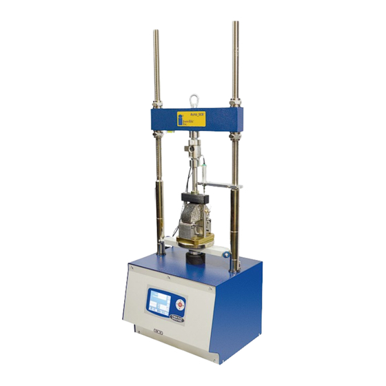
(SCB) tests described in AASHTO TP 124 (recommended by University of Illinois, I-Fit) and ASTM D8044 (recommended by Louisiana State University). Auto_SCB also perform a variety of mechanical property tests on asphalt mixtures such as IDT strength, Marshall Stability, and IDEAL-CT. - Page 9 InstroTek Machine Components Reaction Bar Load Cell LVDT Loading Rod SCB Jig Control Screen (Touch Screen) Fig 1. Auto_SCB Load Frame with SCB Jig...
- Page 10 InstroTek Reaction Bar Load Cell Loading Rod LVDT Lottman Breaking Jig Fig 2. Auto_SCB Load Frame with Lottman Breaking Jig...
-
Page 11: System Location
InstroTek 2. System Location When setting up this unit, please select a location that can meet the minimum requirements below. 1. The unit is designed to be a bench-top unit. Provide adequate space for the user to utilize the control screen and insert the SCB jig from the front of the load frame. -
Page 12: System Setup
Channel 1, LVDT into Channel 2. 6. Ensure that the nuts on either side of the reaction bar are tightened by hand. 7. Power ON the Auto_SCB using the switch located on the right side of the device next to the power cord. - Page 13 InstroTek Reaction Bar and LVDT Height Adjustment The following steps will guide you through positioning the reaction bar and LVDT to work properly with the SCB or Lottman Breaking jig: 1. Loosen the top bolts of the reaction bar to allow the bar to move freely upward.
- Page 14 InstroTek the jig to slide in and out when in the HOME position with the LVDT in place. NOTE: Tighten the LVDT holder thumb screws finger tight to prevent damaging the LVDT.
-
Page 15: Jig Setup
InstroTek 5. Jig Setup The SCB jig is designed to comply with the requirements of both the I-FIT and LSU SCB standards. The difference in the jig for the standards is the spacing between the rollers. The I-FIT (AASHTO TP 124) test requires an 120 mm spacing while the LSU (ASTM D8044) test requires an 127 mm spacing. -
Page 16: Main Menu
InstroTek 6. Main Menu The Main Menu allows the user to select the main functions of the machine. The main functions are: Cracking Test Position Cracking Test Active alarms System config. Ram Position Test archive Control panel Select an item with the touch-screen: Scroll through the menu until the desired menu item is highlighted and select the item by touching the screen. - Page 17 InstroTek Select an item with the keypad: Scroll through the menu using the arrow keys until the desired menu is highlighted. Push the Enter key to select an item.
-
Page 18: Status Bar & Symbols
InstroTek 7. Status Bar The bottom of the main screen contains the status bar. The left side of the status bar provides the current software version installed on the machine. The center of the bar provides the current status of the machine. The right side provides the current date and time. -
Page 19: Operation
InstroTek 8. Operation This section will provide a general guide to set up, run, and record the data for a test in the Auto_SCB Sample Preparation for SCB 1. Prepare specimens according to the instructions in the relevant standard. a) I-FIT – AASHTO TP 124 b) LSU –... - Page 20 InstroTek NOTE: A wet saw, tile saw, or table saw with a masonry bit may be used to consistently cut the notch. 4. Insert a specimen into the SCB Jig (Figure 4). Adjust the horizontal alignment bolt such that the specimen is centered on the roller supports.
- Page 21 InstroTek Sample Preparation for IDEAL-CT and TSR 1. Prepare specimens according to the instructions in the relevant standards. If no standards are specified, ASTM D6925 or AASHTO T 312 can be used. NOTE: Specimens may be prepared using the gyratory compactor, or cores cut from the field or slabs from a laboratory compactor.
-
Page 22: Running The Test
InstroTek 9. Running the Test 1. Press to begin setting up a test. 2. The main test screen will be displayed (as seen below). Configure Inputs (LVDT, Load Cell) Sample ID Configure Selected Loading Standard History Start Test Exit to Main... - Page 23 InstroTek Loading Rod Contact LVDT Support Top Loading Horizontal Adjustment Perpendicular Alignment Bar Roller Support Fig 4. SCB Jig with Asphalt Specimen b. IDEAL /TSR - Insert a specimen into the Lottman Breaking Head jig (Figure 5). Raise the top loading bar and center the specimen on the bottom loading bar.
- Page 24 InstroTek LVDT Support Top Loading Bottom Loading Bar Fig 5. Lottman Breaking Jig with Asphalt Specimen 5. Insert the test jig with the specimen into the test frame, aligning the slot in the bottom of the jig with the centering pin on the machine ram.
- Page 25 InstroTek 8. Enter a Sample ID by touching the Sample ID Text box on the screen; an on-screen keypad will display. Press the enter key when complete. 9. Select a standard (test method). By default, AASHTO TP 124 (I-FIT), ASTM D8044 (LSU), TSR, IDEAL-CT, and Marshall Stability are stored in the machine memory.
- Page 26 InstroTek Configuration section) if the position is too close or too far away to the load rod. 13. Center and align the loading rod and the top plate of the jig. 14. Ensure that the nuts on top and bottom of the reaction bar are tight.
-
Page 27: Results
AASHTO TP 124 (I-FIT) results can be analyzed using data provided by the University of Illinois (apps.ict.illinois.edu/software). IDT Strength, Marshall Stability and Flow, and IDEAL-CT values are calculated in the Auto_SCB Analysis software available from InstroTek. -
Page 28: Device Configuration
InstroTek 11. Device Configuration The machine is capable of different loading histories, such as the AASHTO TP 124 (I-FIT), ASTM D8044 (LSU), AASHTO T 283, IDEAL-CT, and Marshall Stability, as well as other loading histories. The machine can be programmed for different loading histories using the information in this section. - Page 29 InstroTek Parameters and Test Methods Test Methods (Standard) I-FIT LSU* IDEAL-CT** TSR** (Illinois)* Parameter ASTM ASTM AASHTO T AASHTO D8044 Proposed TP124 0.05 0.05 Pre-load rate mm/minut Disabled kN/sec kN/sec Pre-load force 0.1 kN 0.045 kN 0.1 kN ̶ Pre-load pause...
-
Page 30: Channel Allocation
InstroTek 12. Channel Allocation The machine is capable of controlling loading rate by using: 1) displacement, or 2) force control. The load is recorded by the load cell. The recorded displacement can be measured using an encoder attached to the ram or an external LVDT, which is independent of the control method (recommended). - Page 31 InstroTek In the channel allocation, the channels can be changed by touching channel numbers. channel numbers correspond to the numbers on the connections on the left side of the machine. c. To output the LVDT displacement to the data file...
- Page 32 InstroTek e. Return to the main test screen to confirm the changes by pressing i. LVDT position will be shown on this screen if the Displacement channel is Enabled. This can be verified by moving the LVDT in/out. ii. Load cell can be verified by pressing on the load cell by hand to see if the load changes.
-
Page 33: Data Storage & Printing
InstroTek 13. Data Storage and Printing 1. Press to enter the screen below to store and print the rut depth history. Print the test results with a USB printer Save the (PCL test results compatible) to the USB thumb Selection of drive. - Page 34 InstroTek will be named with the “test description” name (set in TEST SETUP), and will include the test date and time. 6. Press to return to the previous screen.
-
Page 35: Alarms
Previous alarm How to confirm and reset an alarm Scroll through the list of the active alarms until the desired alarm is shown. Press to confirm and reset the alarm. If the alarm cannot be cleared, contact InstroTek for instructions. -
Page 36: Manually Positioning The Ram
InstroTek 15. Manually Position the Ram This function allows the user to position ram. This function is useful for setting up the height of the ram for different testing jigs and positioning the ram for calibration of the load cell. -
Page 37: Test Archive
Home and Test positions and the data acquisition rate. The channel configuration allows the verification and calibration of the measurement sensors on the machine. Contact InstroTek for instructions on how to change parameters in the System Configuration not mentioned in this manual. These are set at the factory and should only be changed after contacting InstroTek. - Page 38 InstroTek Default System Configuration Parameters Parameter Value Description File that records PID settings Run log file Base and error for the loading history Allows data to automatically Auto saving Disabled be saved to a USB thumb drive Graph Data acquisition rate (1, 2, 5,...
- Page 39 InstroTek Displacement from the bottom of the stroke of the HOME ram to the HOME position for position setting up the jig and specimen Displacement from the bottom of the stroke of the TEST position ram to the TEST position for...
-
Page 40: Channel Configuration & Calibration
InstroTek 18. Channel Configuration & Calibration Follow the instructions below to verify and calibrate the measurement sensors, such as LVDT and load cell. 1. Press on the main menu to enter system configuration. 2. Select the appropriate profile. a. Press to change the profile. - Page 41 InstroTek 6. Select a desired channel to see the channel setup parameters below. NOTE: Do not change these parameters, unless instructed by InstroTek (1-919-875-8371). Select to go to the calibration screen below.
- Page 42 InstroTek Select move up/down loading/unloading a load cell. The reaction bar can be moved to fit the verification equipment. Select to go to the verification screen below. 10. Select to go back to the calibration screen (step 5). Press again to return to the channel setup screen (step 11.
-
Page 43: Control Panel
Date and time. International settings. Units (Metric/English Standard) Touch screen calibration. Network connection. NOTE: The following settings are set at the factory and should not be changed unless directed to do so by InstroTek. Password change (password protected). Software maintenance (password protected). -
Page 44: Maintenance
4. Annually: a) Clean all machine parts with a mild soap or household cleaner. b) Calibrate the following items: Load Cell (ASTM E-4) External LVDT (ASTM D-6027) c) Check for updates to the firmware or testing software. Contact Instrotek for assistance. -
Page 45: Index
InstroTek 21. Index AASHTO ..........13, 15, 23 Alarms ..............29 Channel Allocation ......... 24 Channel Configuration &Calibration ... 34 Confirm & Reset an Alarm ......29 Configuration Parameters ......32 Control Panel ............ 37 Data Storage & Printing ........27 Device Configuration ........ - Page 46 InstroTek Loading History Parameters ......22 Lottman Breaking Jig ......4, 7, 18 LSU ..............9, 13 LVDT Height Adjustment ........7 Machine Components ........3 Main Menu ............10 Main Menu Functions ........10 Maintenance ............ 38 Manually Position the Ram ......30 Operation ............
-
Page 47: Warranty
InstroTek 22. Warranty InstroTek, Inc. extends a 1-year warranty on the Auto_SCB™ to the original purchaser of this equipment. This warranty covers defects in material, workmanship, and operation under the conditions of normal use and proper maintenance. This WARRANTY DOES NOT cover the replacement of the parts due to improper setup. - Page 48 InstroTek Contact Information Innovators in Instrumentation Technology www.InstroTek.com | (919) 875-8371 | sales@InstroTek.com Research Triangle Park, NC | Austin, TX | Bensalem, PA | Grand Rapids, MI | Denver, CO | Las Vegas, NV | Concord, CA...
- Page 49 Contact us for top quality, best value and superior service! email: sales@instrotek.com visit: InstroTek.com ª Call a loCaTIon near you: Headquarters: research Triangle Park, nC phone: 919.875.8371 Bensalem, Pa phone: 215.645.1064 Grand rapids, MI phone: 616.726.5850 ª Denver, Co phone: 303.955.5740 austin, TX phone: 512.452.8848...
Need help?
Do you have a question about the Auto_SCB and is the answer not in the manual?
Questions and answers