Table of Contents
Advertisement
Quick Links
®
innovators in instrumentation technology
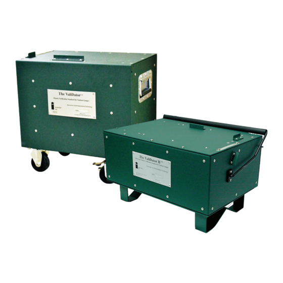
Nuclear Gauge Calibration and
Verification System
OPERATING MANUAL
www.InstroTek.com
Advertisement
Table of Contents

Related Manuals for InstroTek ValiDator

Summary of Contents for InstroTek ValiDator
- Page 1 ® innovators in instrumentation technology Nuclear Gauge Calibration and Verification System OPERATING MANUAL www.InstroTek.com...
- Page 2 © 2018 InstroTek, Inc. ValiDator Nuclear Gauge Moisture/Density Verification and Calibration System Manual Revision 6...
-
Page 4: Table Of Contents
InstroTek 1. Table of Contents **************************************** 1. INTRODUCTION 2. ACCESSORIES AND APPLICATION 3. SOFTWARE INSTALLATION 4. SYSTEM OPERATION 5. THEORY OF OPERATION 6. INDEX 7. WARRANTY... -
Page 5: Introduction
ValiDator is the first and the only traceable portable verification and calibration system in the industry. InstroTek, Inc. would like to thank you for selecting the ValiDator as your field verification and calibration device. The ValiDator Technology is covered by US Patent numbers 5,923,726 and 6,050,725 including International patents. - Page 6 Verification Procedures for Gauges Not Supported page 20. MC2: InstroTek currently does not support verification of this gauge. Please contact InstroTek for more information on this gauge model or refer to manual section Verification Procedures for Gauges Not Supported page 20.
- Page 7 These gauges, like 4640, operate with two independent measurement systems. A special optional software application is required for these gauges. 4640: Not supported by the ValiDator I. The ValiDator II available from InstroTek is specifically designed for verification and calibration of 4640B gauges and 3450 in the Thinlayer mode.
- Page 8 Use proper lifting techniques when loading and unloading the ValiDator. Be aware of heavy machinery operating in the area of testing. Important: Follow the requirements of your nuclear materials license when...
- Page 9 Backscatter (BS) and Depth 12 measurements, due to the relatively lower precision at these positions. Verification Process Align gauge on the ValiDator. For lowering the Source rod, slide the gauge back until the rod is over the access hole. (See Gauge Placement page 8) Set count time for four (4) minutes.
- Page 10 Complete a four (4) minute reading and record the gauge results WD, M, DC and MC on the ValiDator Evaluation Form (page 10). Make additional blank copies of this form for future use. The Wet Density (WD) and Moisture (M) readings from the gauge should fall between the range indicated on the gauge specific ValiDator Calibration Data Table.
- Page 11 Gauge Placement Nuclear gauges differ between manufacturers. It is important to align each gauge using the positioning stops on the top and left of the ValiDator. Backscatter & Moisture Readings All Backscatter (Depth 0) and Moisture readings should be taken with the gauge...
- Page 12 Slide the gauge back until you can drop the source rod in the hole on top of the ValiDator. Once the source rod drops in the hole, make sure to keep the gauge flush with the left stop and slide the gauge back away from the...
- Page 13 InstroTek ValiDator Evaluation Form ValiDator S/N ___________________________ Verification/Calibration Date: ____________ Gauge S/N ___________________________ Operator: ____________ Gauge Model ___________________________ Daily Standard Counts DS________________________ MS________________________ Calibration Standard Counts DS________________________ MS________________________ Establish these counts using the average counts from the results of a Stat Test, 20- minute count or (5) 4 min.
- Page 14 InstroTek Example of Gauge Calibration Report...
- Page 15 InstroTek Example Gauge Calibration Report Key 1) Make (CPN, Humboldt, InstroTek or Troxler) 2) Model 3) Serial Number 4) Calibration Standard Counts 5) Calibration Date 6) Factory Density Constants (A, B, C Parameters) 7) Calibration Block Densities lb. /ft3 or kg/m3...
-
Page 16: Accessories And Application
InstroTek 2. ValiDator Accessories and Application Before using the ValiDator, it is recommended that the user read this manual and understand the operation of this system. List of Equipment & Accessories User Guide ValiDator (Calibration Box) ValiDator Density Data (Laminated Sheets) - Page 17 Read-only Memory) in their gauges. Calibration constants may be entered into a gauge (CPN MC3, MC3 Elite, MC1 Elite, Humboldt EZ and SD, InstroTek 3500 and Troxler 3430, 3440, 3430 Plus and 3440 Plus) using the operating keypad. Units that employ EPROM’s (Troxler 3411 and Humboldt 5001 series) may operate using density tables while an EPROM is programmed and mailed for installation.
-
Page 18: Software Installation
Access codes will be needed to complete installation. NOTE: ValiDator and its’ associated software is licensed to a single user. Use of the ValiDator and its’ associated software is not allowed for calibration of gauges from other organizations. - Page 19 InstroTek Follow the Install instructions. Follow prompts. Moving Software VeriFier software may only be installed on one computer. Moving to another computer is possible. Please contact InstroTek for procedures and access codes.
-
Page 20: System Operation
It is recommended that one individual in an organization be responsible for the calibration process. The Verifier Software with counts taken on the ValiDator can be used to generate new moisture and density calibration constants for the gauge. Resources: InstroTek VeriFier Software, PC, Completed Evaluation Form, *Density... - Page 21 InstroTek Moisture Calibration The ValiDator is engineered to provide moisture verification and calibration in pcf or kg/m³. The nuclear gauge moisture calibration process differs from density in that the moisture calibration is a straight line and rarely will need to be re-calibrated.
- Page 22 Take a Daily or Calibration Standard Count and record on ValiDator Evaluation Form. Do not take the Standard Count on the ValiDator. Align the density gauge on the top of the ValiDator using the specific guides on top of the ValiDator device. (See Gauge Placement page 8) Backscatter readings should be measured in contact with alignment stop.
- Page 23 2. When you receive the gauge, take a four-minute Standard Count. Use the following form or generate your own spread-sheet program. 3. Take four minute WD and M readings on the ValiDator at each depth and enter in column A and D for density and moisture, as baseline readings.
- Page 24 InstroTek Gauges Not Supported Verification History Profile Gauge Model Date: Gauge S/N: Operator: ValiDator S/N: (A) Baseline (B) Test (C) % Diff. (E) Test Date Depth Density Density B - A Baseline Moisture Diff. Moisture E - D...
- Page 25 (2)-four minute counts and record the average on the form. Use the ValiDator Density Table to evaluate the Wet Density and Moisture of the depth being tested for the pass/fail range. If the Wet Density and Moisture fall within this range the gauge passes the verification process.
- Page 26 To utilize the features of the VeriFier Software, you must enter the current gauge calibration and ValiDator density data into the software. Follow Step I: Entering Gauge Calibration Data on page 25 and Step II entering ValiDator Densities on page 26.
- Page 27 InstroTek Calibration Procedures The calibration process utilizes the optional VeriFier Software. Contact InstroTek to obtain your specific password for operating this program. Note: Only trained, qualified and experienced users should perform the Calibration and you should follow the requirements of your nuclear materials license for operating, maintaining and using your gauge.
- Page 28 From the Gauge pull down menu, select New if this is the first time this gauge data is being entered. Enter Password. (This was obtained from InstroTek on installation. Please contact InstroTek if lost.) Enter Gauge General Information; Make, Model (Select the model...
- Page 29 ValiDator function is available. Insure that before a calibration is attempted that the correct ValiDator is selected.) 1. Select ValiDator from the pull down menu, and Select New. Enter the ValiDator Serial number, and From the Model pull down, select the appropriate model from the laminated ValiDator Calibration Table.
- Page 30 Step III: Entering Calibration Counts (This procedure will calculate new Calibration constants from the counts taken on the ValiDator. It is extremely important to accurately input this data.) From the Calibration pull down menu, select CaliBrate and enter the Password at the prompt. Contact InstroTek for a misplaced password.
- Page 31 Calibration Date This is the date that the calibration was done. Gauge Count Density Counts from each depth taken on the ValiDator. Depths 0 and 12 are the average of (2) four-minute readings. Calib. Moisture Count Moisture count taken at backscatter...
- Page 32 InstroTek Calibration and Verification Uncertainties ASTM DD7759 requires the reporting of verification and calibration uncertainties. The software calculates and reports uncertainty budgets for each gauge verified and calibrated.
- Page 33 InstroTek...
- Page 34 InstroTek...
- Page 35 Programmable Read Only Memory) Chip. Fax or email the new constants report to InstroTek and we will program a chip for you. On receipt of the programmed chip remove the old chip noting the position of the reference notch on the top.
- Page 36 The Gauge Calibration Sheet from the calibration in the gauge during verification. Fees: There is a fee for each gauge that requires an EPROM Programmed. Freight: InstroTek will ship using regular shipping methods (average two or three day delivery). Air shipment is available upon request at applicable rates.
- Page 37 Ctrl+E. 1. To insure proper programming and installation of EPROM and Calibration Constants, the gauge should be verified on the ValiDator using the ValiDator Evaluation Form. Once the new constants are entered, place the gauge on the ValiDator and make sure the density readings obtained with the gauge are within the required ranges provided on the laminated ValiDator sheets.
- Page 38 InstroTek Calculate Density This functions as the processor of a gauge in calculating a density from a raw count. Calculates the count ratio and uses the calibration counts to calculate the density. Verification of field readings may be accomplished with using the raw counts to check for operator-induced errors, (i.e.
-
Page 39: Theory Of Operation
Verification Theory ASTM and AASHTO requirements dictate calibration verification at an interval of 12 months. The ValiDator is a known and stable density reference that can be used for verification of gauge calibration accuracy. The ValiDator device is calibrated by InstroTek, assigning reference densities to each of the measurement depths. - Page 40 The Validation and Calibration process simulate counts to replicate the number of blocks used in the most recent calibration. CPN, InstroTek and Troxler use the Three-block method and Humboldt uses the Five-block method.
-
Page 41: Index
InstroTek 6. Index 3-Block/5-Block Method ......... 37 AASHTO ..........2, 17-18, 36 Accessories ............13 Calculate Density ........34-35 Calibration............17 Calibration Process ....7, 13, 17, 24, 36 Data Evaluation ..........22 Density ..........4, 7, 9-10, 47 Density Calibration ........17, 36 Entering Calibration Counts ...... - Page 42 Moisture Calibration ......... 37 Verification Theory ..........36 Upgrading Software ........15 User Guide Information ........4 ValiDator Evaluation Form ......10 Verification History Profile ....... 21 Verification Procedures ........18 Gauges not Supported ........20 Verification Process ....... 6, 13, 17...
-
Page 43: Warranty
InstroTek products are guaranteed against defective material and workmanship for a period of 12 months from the date of receipt by the customer. InstroTek will replace, free of charge, any part found to be defective within the warranty period. This warranty is void if inspection shows evidence of abuse, misuse or unauthorized repair. - Page 44 InstroTek Contact Information Innovators in Instrumentation Technology www.InstroTek.com | (919) 875-8371 | sales@InstroTek.com Research Triangle Park, NC | Austin, TX | Bensalem, PA | Grand Rapids, MI | Denver, CO | Las Vegas, NV | Concord, CA...
- Page 45 Contact us for top quality, best value and superior service! email: sales@instrotek.com visit: InstroTek.com ª Call a loCaTIon near you: Headquarters: research Triangle Park, nC phone: 919.875.8371 Bensalem, Pa phone: 215.645.1064 ª Grand rapids, MI phone: 616.726.5850 Denver, Co phone: 303.955.5740 ª austin, TX phone: 512.452.8848...
Need help?
Do you have a question about the ValiDator and is the answer not in the manual?
Questions and answers