
Subscribe to Our Youtube Channel
Related Manuals for RMG ERZ2000-DI Series

Summary of Contents for RMG ERZ2000-DI Series
- Page 1 ERZ2000-DI ERZ2000 ERZ2000-DI DI Flow Computer Series Flow Computer Series Flow Computer Series OPERATING MANUAL Reliable Measurement of Gas Issued: 2017, DECEMBER 15 Version: Firmware version: 1.0...
- Page 2 Manufacturer Contact our customer service department for technical information. Address RMG Messtechnik GmbH Otto-Hahn-Straße 5 D-35510 Butzbach (Germany) Main office +49 6033 897 – 0 Service +49 6033 897 – 127 Spare parts +49 6033 897 – 173 +49 6033 897 – 130 Email service@rmg.com...
-
Page 3: Table Of Contents
TABLE OF CONTENTS TABLE OF CONTENTS 1 ABOUT THIS MANUAL ..... 1 Structure of the manual ................1 Purpose of the manual ................2 1.2.1 Abbreviations ......................2 1.2.2 Structure of notices ....................4 1.2.3 Working with the device ..................5 1.2.4 Risk assessment and minimization ................ - Page 4 TABLE OF CONTENTS 2.7.5 Archive ......................... 66 2.7.6 Alarm, warning message ..................70 2.7.7 Highest load display ..................... 72 Time system ....................72 2.8.1 IB Time, date ......................72 2.8.2 IC Time synchronization ..................72 3 ELECTRICAL CONNECTIONS ..73 3.1.1 Equipment variants ....................
- Page 5 TABLE OF CONTENTS Error settings ................... 108 6.1.1 YL error messages ..................... 108 Error list ....................109 APPENDIX ......... 116 Updating software ................... 116 Advance information ..................116 Software identification ..................116 Updating software ....................117 Installing BIOS ....................119 Activation after software update .................
-
Page 7: About This Manual
1 ABOUT THIS MANUAL 1 About this manual 1.1 Structure of the manual The first chapter of this manual essentially comprises four parts. Safety-relevant general specifications are provided in the first part. They must be observed for safe operation. The symbols used in the manual and the structure of notices are presented, and a risk assessment are also provided. -
Page 8: Purpose Of The Manual
1 ABOUT THIS MANUAL 1.2 Purpose of the manual This manual provides information that is necessary for fault-free and safe opera- tion. The ERZ2000-DI was designed and produced according to the state of the art and generally recognized safety standards and directives. However, its use can entail dangers that are avoidable by complying with this manual. - Page 9 1 ABOUT THIS MANUAL ETH1 / ETH 2 Ethernet interface 2 /2 Ethernet technology enables a data exchange between the con- nected devices in the local network. SNTP (Simple) Standard (NPT = Network Time Protocol) for synchroni- zation of clocks in computer systems Signal to Noise Ratio SoS (VoS) Speed (Velocity) of Sound...
-
Page 10: Structure Of Notices
1 ABOUT THIS MANUAL 1.2.2 Structure of notices The following notices are used: Danger This warning notice informs you of imminently threatening dangers that can arise due to misuse/operator error. If these situations are not avoided, death or severe injuries can occur. warning This warning notice informs you of potentially dangerous situations that can arise due to misuse/operator error. -
Page 11: Working With The Device
All notices in the manual must be observed. Use of the flow computer ERZ2000-DI is only permitted in accordance with the specifications in the operating manual. RMG assumes no liability for damages arising due to disregard of the op- erating manual. Danger... - Page 12 The flow computer ERZ2000-DI complies with current standards and regu- lations. However, danger can arise with misuse. 1.2.3.2 Dangers during commissioning Initial commissioning The initial commissioning must only be carried out by qualified personnel or RMG service personnel. Manual ERZ2000-DI · EN1.2 · 2017, December 21st...
- Page 13 1 ABOUT THIS MANUAL Note In accordance with Article 15 of the German Ordinance on Industrial Safety and Health (BetrSichV), Article 5 of German Social Accident Insur- ance (DGUV) REGULATION 3 "Electrical systems and equipment” and generally recognized good engineering practices, particularly the VDE standards VDE 0100-100 "Construction of low-voltage systems”...
- Page 14 1 ABOUT THIS MANUAL Caution In general, the replacement of a flow computer ERZ2000-DI must only be carried out by RMG Service. 1.2.3.3 Dangers during maintenance and repair Operating personnel The operating personnel use and operate the device in the scope of the intended use.
-
Page 15: Risk Assessment And Minimization
The capacity to be able to correctly estimate dangers and risks when working with the flow computer ERZ2000-DI and all connected devices. Training / education by RMG for work with gas measuring devices. Education / instruction in all national standards and directives to be complied with for the work to be carried out on the flow computer ERZ2000-DI. -
Page 16: Applicability Of The Manual
This manual describes the flow computer ERZ2000-DI. The ERZ2000-DI is only part of a complete system. The manuals of the other components of the system must be observed. If you find contradictory instructions, contact RMG and/or the manufacturers of the other components. -
Page 17: Transport
1 ABOUT THIS MANUAL 1.2.5.2 Dangers of operation in Ex areas Danger The flow computer ERZ2000-DI must be used exclusively in fault-free and complete, original condition. If you make technical changes to the device, safe operation can no longer be guaranteed. Ensure that the appropriate explosion protection is provided for the connection of all sensors or other devices that are used in explosion- prone areas! -
Page 18: Disposal Of Packaging Material
Avoid extended periods of storage. After storage, inspect the device for damage and test for correct function. Contact the RMG service department to arrange for inspection of the device after a storage period of longer than one year. For this purpose, send the device to RMG. -
Page 19: Function
1 ABOUT THIS MANUAL 1.3 Function The flow computer ERZ2000-DI is designed to operate various sensors, particu- larly flow rate and gas analysis sensors, evaluate their signals or adopt and deter- mine resulting operating and nominal volume flows. The resulting calculation varia- bles can be represented in a graph and checked via alarm output, etc. -
Page 20: Overview
1 ABOUT THIS MANUAL The ERZ2000-DI records analogue and digital values, such as frequencies, re- sistances, etc. Then these are assigned to physical variables, such as operating volume flow or temperature. Further processing of these values takes place in the ERZ2000-DI, where, for example, gas characteristics and standard volume flow are calculated from these basic values. -
Page 21: Areas Of Application
1 ABOUT THIS MANUAL 1.5 Areas of application The essential area of application is the recording and metering of flow rates for custody transfer in natural gas flow measurement technology. The device can be delivered in two different versions of the software, each with a separate approval as: Status flow computer for natural gas (ERZ2004-DI) Calorific value flow computer for natural gas (ERZ2104-DI) - Page 22 1 ABOUT THIS MANUAL Danger Only use the ERZ2000-DI in its original condition. When connecting sensors and other devices in explosion-prone areas, ensure that the appropriate explosion protection is provided for these components. The specified maximum values in the certificates issued for these components must be observed.
-
Page 23: Seal Diagram For Devices With Mid Approval
1 ABOUT THIS MANUAL 1.5.2 Seal diagram for devices with MID approval The ERZ2000-DI leaves the company with a setting agreed upon with the cus- tomer, which is protected from "significant" modifications by seals and metrological sealing, or it leaves the factory without seals. In the latter case, a calibration official must provide the device with seals according to the desired settings in accordance with the seal diagram. -
Page 24: Signature, Software And Hardware Data
1 ABOUT THIS MANUAL View A View B View D View C Metrological seal Metrological seal Figure 3: Seal diagram - sides A, B, C, D Seal or sealing wire Seal or sealing wire Connector housing with seals: Figure 4: Seal diagram - rear 1.5.3 Signature, software and hardware data The ERZ2000-DI offers the option of marking recorded data with an accompanying... -
Page 25: Introduction
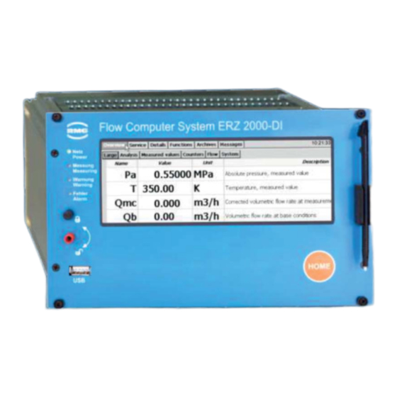
2 INTRODUCTION 2 Introduction 2.1 Operation 2.1.1 Front panel Figure 5: Front panel The following display and operating elements are located on the front panel: Green LED Continuously illuminated: Voltage indicator. (Network) Blinking light: User or calibration lock opened Orange LED Continuously illuminated: Meter is connected and delivers (measure- measurements. -
Page 26: Operation On The Touch Screen
2 INTRODUCTION Custody Sealable rotary switch, transfer when the limit stop in the clockwise direction is switch reached, the custody transfer lock is open, when the limit stop in the counterclockwise direction is reached, the custody transfer lock is closed USB interface For connection of USB components (e.g. - Page 27 2 INTRODUCTION Figure 6: Operation of the ERZ2000-DI Very simple adjustment takes place with the browser available on the PC (e.g. In- ternet Explorer, Firefox, etc.), which essentially corresponds to operation of the touchscreen. In addition, display on the PC enables the startup of a wizard directly in the browser for convenient commissioning.
- Page 28 2 INTRODUCTION Figure 7: Rear side of the ERZ2000-DI and Ethernet interfaces Caution Then the ERZ2000-DI can only be integrated into an existing network if the network permits integration of third-party devices. Protected company networks may prohibit this access. Contact your IT department to discuss how you can integrate the ERZ2000-DI into your company network.
- Page 29 2 INTRODUCTION address can be read on the ERZ2000-DI. For this purpose, proceed as follows after starting up the device: Select the following with the stylus: 1. The ERZ2000-DI logs in after start-up with the following screen. Select the "Functions" tab in the upper part of the display. Figure 8: ERZ2000-DI Start page Manual ERZ2000-DI ·...
- Page 30 2 INTRODUCTION 2. Then select the TCP/IP tab. Figure 9: Functions menu Manual ERZ2000-DI · EN1.2 · 2017, December 21st...
- Page 31 2 INTRODUCTION 3. After activation, the screen below appears. Figure 10: TCP/IP menu Check whether you are working with interface 1 (ETH1) or 2 (ETH2) and adjust this setting in the selection menu (please activate) accord- ingly. Check the DHCP setting of the interface. If a DHCP server is available in the network, the IP address is as- signed automatically when "yes"...
- Page 32 2 INTRODUCTION Figure 11: Home page after entry of the TCP/IP address Note If you work with Microsoft Internet Explorer – before the wizard can be started for simplified operation – the compatibility status of the web browser must be checked and adjusted as necessary. If you are using Microsoft Internet Explorer, the compatibility view can be adjusted under "Extras"...
-
Page 33: Operation On The Home Page
2 INTRODUCTION 2.1.4 Operation on the home page The home page can be operated with a mouse and keyboard in the accustomed manner. Operations are equivalent to those on the touchscreen of the ERZ2000-DI and are adopted accordingly. For instance, the TCP/IP addresses can be queried here. -
Page 34: Adjustment Of The Erz2000-Di Via Wizard
2 INTRODUCTION 2.2 Adjustment of the ERZ2000-DI via wizard Adjustment of the ERZ2000-DI preferably takes place using a wizard. For this pur- pose, it must be activated on the home page: Figure 13: Starting the wizard After activation of the "Start wizard" field circled in green, the settings tool of the ERZ2000-DI appears. - Page 35 2 INTRODUCTION The wizard is a component of the ERZ2000-DI and stored internally. This also ap- plies for all documents and images integrated in the wizard. They are not listed here again. The wizard and all integrated documents and images, therefore, are an es- sential part of the documentation.
- Page 36 2 INTRODUCTION Caution Simplified adjustment with the wizard is basically only possible with an open calibration switch of the ERZ2000-DI. However, the notice on removal of seals (chapter 1.5.2 Seal diagram for devices with MID approval) must be observed! If the calibration switch is closed - for legal custody-transfer purposes - almost no settings are possible on the wizard screens.
- Page 37 2 INTRODUCTION The "Service” setting always shows all settings menus and settings possibilities, regardless of settings already made by the user. These settings options can be ed- ited on the following wizard screens in the "Service" setting, although they are en- tirely unnecessary for the overall settings of the ERZ2000-DI.
-
Page 38: Browser Home Page And Coordinate System
2 INTRODUCTION 2.3 Browser home page and coordinate system Links in the home page there is a tree structure that is comparable to Windows Ex- plorer. The relevant menu is opened by clicking on one of the : measurements, components, ... In the process, a symbol change from (bottom menu item) takes place and various sub-menus can be selected by clicking on such as overviews, reassessment, gas properties, etc. - Page 39 2 INTRODUCTION This representation can be activated in the display of the ERZ2000-DI on the touchscreen: 1. Activation of the "Overview" tab 2. Activation of the "Large" tab The displayed parameters can be changed by activating edit after the relevant se- lection.
-
Page 40: Further Specifications In The Home Page
In the right-hand window, the following can also be seen in the upper lines (Figure 20: Top lines in the menu): Figure 20: Top lines in the menu Top line: 1. RMG Messtechnik 2. ERZ2000-DI 3. 1.1.0 Firmware version 4. 2017 Year of manufacture of the ERZ2000-DI 5. - Page 41 2 INTRODUCTION Note If the live browser is activated (see below); For field 9: Time The time must change in the seconds! A live connection is only provided thereafter. All values, not only the values shown in Figure 16: "Overviews " menu are updated "online"...
- Page 42 2 INTRODUCTION 3. Service Shows the user profile. The menu NA Wizard home page can be opened by clicking in the adjacent field Figure 22: User profile (For more information, see wizard) " " " " 6. Error display Pending errors are continuously displayed here. Here: "M54 Calibration lock"...
- Page 43 2 INTRODUCTION Live browser The live browser is activated and all data (such as time) is updated continuously. Clicking on deactivates the live browser ( ). Furthermore, a heading AB GUI/Overview/Large is shown in Figure 16: "Over- views " menu: The selected measurements or parameters are displayed there.
- Page 44 2 INTRODUCTION The representation of measurements and parameters is shown in other menus. For example, various analytical values are specified in the next menu AC Analysis Overview. Figure 24: "AC Analysis Overview " menu The parameters contain the corresponding live values with a unit (if available) and the jump target that describes the determination and specification of the respective value in a menu.
- Page 45 2 INTRODUCTION Figure 25: "BH Calculation of K coefficient" The parameters on the right side belong to different categories, which is indicated with different colors, identification letters and other symbols in the left part on the right screen in the relevant line. The most important include: Dark yellow Display values, change not possible Custody transfer parameter, can be changed with open cali-...
- Page 46 2 INTRODUCTION All measurements, calculation values, parameters and functions are arranged in a coordinate system. There are several tables with columns and lines in this coordi- nate system. Each table as a (umbrella) term, or a heading, under which all various points which have a logical connection with the term are summarized line by line;...
-
Page 47: Display
2 INTRODUCTION number". Chapters belonging together are summarized under the first letters: AA, AB, AC, AD... / BA, BB, BC, ... / CA, CB, CC, CD..Note The method of counting takes place with letter / number combinations be- ginning with AA = first column 01 = first line Chapters belonging together are summarized under the first letters: AA,... - Page 48 2 INTRODUCTION Explanation of symbols in the Access column: Display values, custody transfer, change not possible Parameter under single code word protection Special case: Code word entry/check General displays, display values, non-custody-transfer Parameters protected by official calibration Freeze value, not editable Interface variable –...
- Page 49 2 INTRODUCTION QW QX Table 1: Coordinate system Displayed parameters Parameters These behave like constants. Editing changes the value of the respective con- stant. Automatically changing values that can be edited These values behave like changing values. Editing will change the initial value of these changing values, e.g.
- Page 50 2 INTRODUCTION Figure 28: Automatically changing value "IC06 PTB trigger" Trigger These values basically have no function in the basic state. A task is assigned and initiated with the editing. After completion of the task, the initiator returns to its basic state.
- Page 51 2 INTRODUCTION Parameter change: There are different ways to change parameters: 1. Fields with an arrow (e.g. specification of the parameter shown in "large") Figure 29: "AB Large" Clicking on the arrow (in the red circle) opens a selection menu (see above). The desired value can be selected from these specification parameters.
-
Page 52: Access Protection For Data And Settings
2 INTRODUCTION With the back arrow of Explorer Figure 33: Back to the main menu you return to the previous menu. In order to familiarize yourself with the settings options and the type of setting, we recommend testing the settings options in the various "menus" in this display with the mouse. - Page 53 2 INTRODUCTION Operater Access protection Without protection, can be used when closed. Calibration switch and closed closed code word must be activated. User Lowest protection Single code Double code Official accepted Calibration lock certifying body certifyer Super user Highest protection Factory setting Figure 34: Hierarchy of access protection The lowest protection level applies with a closed calibration switch and without en-...
- Page 54 2 INTRODUCTION Without influence on measurement and measurement accuracy, Closed e.g. operating point testing resolution Without influence on measurement and measurement accuracy, Single code e.g. specification values, warning limits, plausibility, compari- sons, user protocols Adaptation of gas property tables, has influence on measure- Double code ment, but is then permitted and desired.
- Page 55 2 INTRODUCTION Deactivation of the access protection The access protection can be deactivated with the touchscreen of the ERZ2000-DI (see Figure 35: Deactivation of the access protection) and with the browser (see Figure 23: Error messages). The button "Forget code word" becomes visible in the touchscreen display after clicking on the "Message"...
-
Page 56: Language Setting
2 INTRODUCTION 2.5 Language setting The ERZ2000-DI is normally pre-configured, and the ordered language is set. The wizard also starts automatically in the pre-configured language. However, it may be necessary to change the language. This takes place in the menu ID Display, see Figure 36: ID Display menu. Figure 36: ID Display menu First, select the language in the coordinate ID01 Language;... - Page 57 2 INTRODUCTION Figure 37: Start screen The home screen appears after each restart of the device or after pressing the "HOME" key. This home screen shows the active meters, which are framed in ital- ics with " * " according to calibration authority specifications. The other meters be- come visible with vertical scrolling (right).
-
Page 58: Overview
2 INTRODUCTION Figure 38: Input field The left field is provided for entry of the numerical values; the right field is provided to select a mode. The new numerical value and/or the new mode is adopted with "accept". 2.7.1 Overview Scroll to the top in the overview or tap on the "Overview"... - Page 59 2 INTRODUCTION 2.7.1.2 Analysis Figure 39: Overview -> Analysis sub-menu The calculation process and corresponding input and result values are displayed in this menu. The calculation process of the compressibility number is specified in the first line – GERG 88S in this case. In addition to further gas-specific parameters, the data for the gas composition that varies depending on the selected calculation process is provided here.
- Page 60 2 INTRODUCTION 2.7.1.4 Counters Figure 41: Overview -> Meters sub-menu This menu shows the various meters for the two calculation modes, a color under- line assigns different times or other classifications to the meters. The appendix B) Totalizer in the browser view shows how the meters are handled in the browser display.
-
Page 61: Service
2 INTRODUCTION 2.7.1.6 System Figure 43: Overview -> System sub-menu Various general values are displayed here, including the IP addresses with which you can actuate the device if it is connected to the PC, a PLC, etc. via Ethernet. 2.7.2 Service Figure 44: Service menu The available settings in "Service functions"... -
Page 62: Details
2 INTRODUCTION Figure 45: "Calibrate stylus" service menu / sub-program After the function starts a series of crosses that must be touched in the center is displayed. After this takes place touching the touchscreen again returns to the pre- vious screen. This calibration can take place at any time. -
Page 63: Functions
2 INTRODUCTION Figure 46: Details menu Chapter 2.1.3 Remote control / parameterization explains how parameters can be changed. 2.7.4 Functions Figure 47: "Drag pointer" sub-menu under "Functions" The "Functions" menu opens 6 additional display views, which are presented be- low. The drag pointer function is displayed first. Manual ERZ2000-DI ·... - Page 64 2 INTRODUCTION 2.7.4.1 Drag pointer The absolute minimum and maximum values for the measurements since the last restart or since the last resetting of the drag pointer are shown here. The function can be used for different measurement variables and is specified, for example, with the BC Absolute pressure in the coordinates BC31 Min.
- Page 65 2 INTRODUCTION Figure 49: "Type plate" sub-menu under "Functions" The type plate of the device is displayed in the "Type plate" submenu. This in- cluded further data, e.g. about the electronics (calibration kernel, Bios, WinCE ker- nel), about the meters and their settings (dimensions, pulse value), about the type of gas (composition, velocity of sound) and the environmental and standard condi- tions (pressure, temperature).
- Page 66 2 INTRODUCTION Figure 50: AI Type plate menu 2.7.4.4 Functional test Figure 51: "Functional test" sub-menu under "Functions" The quantities and measurements are recorded and displayed for a defined length of time in the functional test. The functional test is divided into a run-up, the actual test and an after-run.
- Page 67 2 INTRODUCTION Functional test process: Enter four times for the three sections of the functional test. Click on the "Start Time1" button. Then the functional test is run according to the four times. Times that have already elapsed are highlighted green. Blinking green times indicate the functional test progress.
- Page 68 2 INTRODUCTION error (e.g. 1200 seconds = 20 minutes). This also applies for the "On-the-fly cali- bration" function. The coordinates of the menu in detail: HC01 Revision Status Shows the current status of the function (stationary / running) HC02 Time stamp 1 Parameter for starting the test process (run-up start) HC03 Time stamp 2 Parameter for stopping the run-up and starting the ac-...
- Page 69 2 INTRODUCTION Functional test under running conditions Time stamp 1 Time stamp 2 Time stamp 3 Time stamp 4 Pre run Examination Post run Desig- 13-12-2017 13-12-2017 13-12-2017 13-12-2017 Unit Trend nation 15:57:41 15:58:41 15:59:57 16:00:57 Time 22459.647093 59.996115 22519.643209 75.995960 22595.639168 59.996881 22655.636049 0.000000...
- Page 70 2 INTRODUCTION The center row with 3 columns and the test heading (bold) is the result of the func- tion test. The first column displays the initial values, the center column the differ- ences and averages and the third column the stop values. Run-up and after-run are relevant data depending on the logical test times.
- Page 71 2 INTRODUCTION Figure 54: HA Freeze menu The selection of how frequently the freeze process is initiated (HA03 Freeze mode) is: No freeze processes are initiated and the freeze dialog is de- activated. Every second Freeze in second intervals Every minute Freeze in minute intervals at the start of a minute Every hour Hourly freezing at the start of an hour...
-
Page 72: Archive
2 INTRODUCTION Gas month The freeze is initiated in the specified month (coordinate "YA28 Gas month") at the beginning of the specified billing hour and specified day (coordinate "YA27 Gas day"). The billing hour and day must be specified; month and year are specified automatically. - Page 73 2 INTRODUCTION Note Only display is possible on the device; the archive content can also be ex- ported in the Excel-compatible tsv format with the internet browser. Figure 56: "Archive" Call-up of archive data The desired archive group (AG) is selected at the top left. A search time can be entered in the field below it.
- Page 74 2 INTRODUCTION White Error-free measurement Gray Meter/measurement has stopped Blue Substitute value Green Fixed value It is possible to freely define a special archive. The content and recording cycle can be selected arbitrarily by the user. The complete scope of all measurements and values are available via a selection menu for the storage of data, comparable to the selection for the current outputs (Figure 57: Free programmable archive menu).
- Page 75 2 INTRODUCTION Figure 57: Free programmable archive menu Deletion of archives, log books, change buffer, etc. In the menu L Factory setting, sub-menu LE Erasing procedures (Figure 58: Menu LE Erasing procedures), archives, log books, etc. can be deleted. As a Su- per user (see chapter 2.4 Access protection for data and settings) the coordinates LE10 Clear log, LE11 Clear changes, LE12 Clear archive (DSfG archive of the flow computer and registry entry, as well as the DSfG log book), LE13 Hour/day...
-
Page 76: Alarm, Warning Message
2 INTRODUCTION Figure 58: Menu LE Erasing procedures Further details about the archive are provided in the appendix C) Archive assign- ment, depth and identification. 2.7.6 Alarm, warning message Figure 59: "Messages" All messages that have taken place since the last deletion are displayed in differ- ent colors in this field: Manual ERZ2000-DI ·... - Page 77 2 INTRODUCTION Pending alarms, i.e. faults of the custody transfer functions that re- sult in counting in the disturbance meters. General alarms are iden- tified with "A"; internal computer errors are identified with "R". Yellow Current warnings, identified with "W", that refer to an error of a non-custody-transfer function.
-
Page 78: Highest Load Display
2 INTRODUCTION 2.7.7 Highest load display The highest load displays and archives have a dedicated approval and are de- scribed in a separate manual. 2.8 Time system General displays and parameters and all displays and parameters that are re- quired for receiving the time signal are located in the menus IB Time, date and IC External time signal. -
Page 79: Electrical Connections
3 ELECTRICAL CONNECTIONS 3 Electrical connections 3.1.1 Equipment variants The assignment of the connection terminals of the ERZ2000-DI is essentially specified by the compact configuration. However, there are reserves, because a different definition of the terminal assignment is necessary depending on addition- ally installed extension modules. - Page 80 3 ELECTRICAL CONNECTIONS Figure 60: Menu LB Module assembly Device rear wall Since the ERZ2000-DI has a universal configuration, there are more connection terminals that required by the typical device (e.g. a status flow computer). There is a standard assignment of terminals that always use the first pins in consideration of numbering.
- Page 81 3 ELECTRICAL CONNECTIONS Figure 61: Rear wall of the ERZ2000-DI Manual ERZ2000-DI · EN1.2 · 2017, December 21st...
-
Page 82: Terminal Assignment
3 ELECTRICAL CONNECTIONS 3.1.2 Terminal assignment Connection of supply voltage: (bottom left) Figure 61: Rear wall of the ERZ2000-DI X 16 24 V DC Fuse F1 = 2 A 1.0 A 24 W –10% / +15% Typical power con- Max. output sumption (depending on equip- ment) - Page 83 3 ELECTRICAL CONNECTIONS Terminal 1 Current output 1 + Terminal 2 Current output 1 - Terminal 3 Current output 2 + Terminal 4 Current output 2 - Terminal 5 Current output 3 + Terminal 6 Current output 3 - Terminal 7 Current output 4 + Terminal 8 Current output 4 - Terminal 9 Input for Vo with external separator stage + Terminal 10 Input for Vo with external separator stage -...
- Page 84 3 ELECTRICAL CONNECTIONS ERZ2004/2104-DI; X 9 and X 10 are optionally assigned Terminal 1 Ex-option enco + (Vo) Terminal 2 Ex-option enco - (Vo) Terminal 3 Ex-option Vm measuring channel (HFX) + Terminal 4 Ex-option Vm measuring channel (HFX) - Terminal 5 Ex-option Vm comparison channel (HFY) + Terminal 6 Ex-option Vm comparison channel (HFX) - Terminal 7 Ex-option pressure measurement - transmitter (opt.
-
Page 85: Data Interfaces
3 ELECTRICAL CONNECTIONS current loops or the adjustment and/or standardization of signals. Intrinsically safe field devices can be operated within explosion-prone areas with the isolation. For further information, refer to appendix D) Optional Ex input card. 3.1.3 Data interfaces The digital data interfaces are also provided on the basic assembly. These inter- faces can be used as: Service interface Modbus for external data transmission... -
Page 86: Pin Assignment And Usage Recommendation Of The Interfaces
3 ELECTRICAL CONNECTIONS 3.1.4 Pin assignment and usage recommendation of the inter- faces COM 1: Pin assignment Mode: RS 232 Mode: RS 422 Mode: RS 485 +U (+5V DC) +U (+5V DC) +U (+5V DC) TxD-A R/TA A Data RxD-A SGND Signal Ground TxD-B RxD-B... -
Page 87: External Modem Connection
3 ELECTRICAL CONNECTIONS COM 5 (modem): Pin assignment Mode: RS 232 RS 232 with handshake plus DCD (data carrier detect) plus RI (ring indicator). Us- able for MODEM (DFÜ). With connection of a modem, the COM 5 operating mode "Modem" must be se- lected in the wizard. - Page 88 3 ELECTRICAL CONNECTIONS Figure 62: DSfG setting Meaning: Prefix of a command line Echo function deactivated s0=1 Set register 0 to 1, which means the number of alert characters after which the modem answers and establishes the connection, should be 1. Response setting: Hayes Smartmode 300 compatible answers / blind dialing (extension) plus all CONNECT answers...
- Page 89 3 ELECTRICAL CONNECTIONS Figure 63: Menu: IG Serial interfaces The parameters for operation of the serial interfaces (also DSfG-B and Modbus) are adjusted in this menu IG Serial interfaces. The coordinate IG23 is an internal interface that can be used for the original Vo totalizer of an encoder (ENCO).
-
Page 90: Connections
3 ELECTRICAL CONNECTIONS 3.1.6 Connections 3.1.6.1 Input characteristics 2-channel HF volume flow input with pulse metering and frequency measure- ment The appropriate frequency input must be selected in this menu; Inputs 5, 6, 7 and 8 offer higher resolution. Channel 1: Volume measuring channel HF input Measuring range 0.10 Hz to 6.0 kHz Accuracy... - Page 91 3 ELECTRICAL CONNECTIONS Up to 5 analogue inputs, including a pressure measurement input for analog signals and for HARD protocol Current measurement Range 0/4 to 25 mA Resolution 20 bit U max 2.5 V 250 Ω < 15 ppm Measuring time 50 ms Overvoltage protection 6.8 V...
- Page 92 3 ELECTRICAL CONNECTIONS Digital status inputs All inputs are galvanically isolated from the computer, but not from each other. The following can be used as signal transmitters: contact, open collector / drain, active push / pull -U max -I max 13 mA f max 10 Hz...
-
Page 93: Assignment Of "Physical Values
3 ELECTRICAL CONNECTIONS Alarm and warning status outputs U max 24 V DC I max 100 mA P max 100 mW <= 50 Ohm Photomos relay 100 mA 50 Ohm Overvoltage protection 33 V, galvanically isolated 3.1.7 Assignment of "physical values" The assignment of inputs and outputs to "physical values"... -
Page 94: Software And Hardware Identification
3 ELECTRICAL CONNECTIONS 3.1.8 Software and hardware identification Figure 64: Menu IE Software identification There is an additional microcontroller on the base circuit board for control of the FPGA and basic measuring functions whose program is monitored with a check number. - Page 95 ERZ2000-DI is a 20-character-long text field that is already used, there is generally a combination of numbers and letters in the field. The number may also be structured, e.g. "RMG-123/456/789". The software ignores all non-numerical characters when generating the number and the numbers are left in order.
-
Page 96: Transmitters
) is proportional to the mean gas speed and thus the flow rate. The number of rotations, therefore, is a meas- urement for the gas volume flowing through. Figure 66: RMG turbine wheel gas meter TERZ94 Manual ERZ2000-DI · EN1.2 · 2017, December 21st... - Page 97 4 TRANSMITTERS Figure 67: RMG turbine gas wheel meter sectional drawing The rotational movement of the turbine wheel is transferred after reduction to the meter head in which the frequency is normally scanned redundantly with two sen- sors and transmitted as a LF signal. The meter can be optionally equipped with an encoder that can also transmit flow information.
-
Page 98: Ultrasonic Gas Meters
To achieve greater accuracy, multiple ultrasonic transducer pairs are nor- mally used over multiple measuring paths. Figure 68: RMG ultrasonic gas meter USM-GT400 shows an ultrasonic gas meter from RMG and Figure 69: Measuring path arrangement USM-GT400 shows the basic arrangement of ultrasonic trans- ducers with the measuring path. - Page 99 4 TRANSMITTERS Figure 69: Measuring path arrangement USM-GT400 Manual ERZ2000-DI · EN1.2 · 2017, December 21st...
-
Page 100: Special Coordinates
5 SPECIAL COORDINATES 5 Special coordinates Interim results of the highest load determination are shown in the hourly and daily amount menus. In case of faults, they behave as defined by the approval authori- ties. For a user who intends to base billing on these figures, the values cannot be used in case of a malfunction or are at least misleading. - Page 101 5 SPECIAL COORDINATES 1400 4 unsigned integer 32-bit R KI 2 Hourly quantities Last hour Vm 222 m3 1402 4 unsigned integer 32-bit R KI 3 Hourly quantities Last hour Vb 2864 m3 1404 4 unsigned integer 32-bit R KI 4 Hourly quantities Last hour E 34 MWh 1408 4 unsigned integer 32-bit R KI 6 Hourly quantities Last hour Vc 222 m3...
-
Page 102: Documentation
5 SPECIAL COORDINATES 5.2 Documentation The documentation comprises 3 sub-chapters. Additional explanatory information is also provided here along with additional documents that can be opened by dou- ble-clicking on the underlined links. 5.2.1 Matrix … (up to 99) Manual ERZ2000-DI · EN1.2 · 2017, December 21st... -
Page 103: Document Creation
5 SPECIAL COORDINATES An assignment of variables to the menus and the corresponding lines of the coor- dinate system is shown in this matrix. 5.2.2 Document creation … All menus (columns), including the content are listed again here. Automatic adop- tion of this data to the documentation took place earlier, wherein the user saved or Manual ERZ2000-DI ·... -
Page 104: Documentation
5 SPECIAL COORDINATES printed and stapled the pages. Now the user can decide which parts are added to the documentation. Normally, this data is used for internal purposes. 5.2.3 Documentation Documents that offer additional explanations for the specified points beyond the manual. -
Page 105: Parameterization
5 SPECIAL COORDINATES 5.3 Parameterization 5.3.1 Parameterizing data … A list of the relevant parameterizations is provided here. Manual ERZ2000-DI · EN1.2 · 2017, December 21st... -
Page 106: Calibration Data
5 SPECIAL COORDINATES 5.3.2 Calibration data … The custody transfer parameters from all parameters are displayed here. Manual ERZ2000-DI · EN1.2 · 2017, December 21st... -
Page 107: Changes
5 SPECIAL COORDINATES 5.3.3 Changes This menu lists all parameter changes that have been made, sorted by time. Manual ERZ2000-DI · EN1.2 · 2017, December 21st... -
Page 108: Save And Load
5 SPECIAL COORDINATES 5.3.4 Save and load This menu is provided for saving, reading and adjusting the settings of the ERZ2000-DI. Note In particular, backup copies of parameter settings of the ERZ2000-DI can and should be made with this menu, if the device is tested, updated or changed for other reasons. -
Page 109: Other
5 SPECIAL COORDINATES 5.4 Other 5.4.1 Error display Pending errors with error numbers are listed in this menu. Acknowledgment corre- sponding to that of the touch screen is possible. Manual ERZ2000-DI · EN1.2 · 2017, December 21st... -
Page 110: Freeze Values
5 SPECIAL COORDINATES 5.4.2 Freeze values Values of the last freeze process are listed here. Manual ERZ2000-DI · EN1.2 · 2017, December 21st... -
Page 111: Interface Variables
5 SPECIAL COORDINATES 5.4.3 Interface variables Interface variables are variables that transmit custody transfer information or effect the representation of custody transfer information but are not (permanently) sub- ject to custody transfer requirements. Manual ERZ2000-DI · EN1.2 · 2017, December 21st... -
Page 112: Log Book
5 SPECIAL COORDINATES Example ERZ2000-DI is connected to Stream 1. If the measurements of Stream 2, 3, 4 or the test gas are available these data are irrelevant. These values only transport custody transfer data if Stream 1 is displayed and the status = "okay". -
Page 113: Tsv Export
5 SPECIAL COORDINATES 5.4.6 TSV export … All saved archive groups are listed here. They can be opened or saved by double- clicking on the indenture numbers. The "complete" groups no longer change and can be saved. The other groups ("growing") are still growing and thus not com- plete. -
Page 114: Exceptions
6 ERRORS 5.4.7 Exceptions This menu is reserved for internal service purposes. This data can provide infor- mation about the cause of error. 6 Errors Error settings 6.1.1 YL error messages Figure 71: Menu YL error messages The coordinate YL01 Current messages shows all pending (active) messages in 2-second intervals. -
Page 115: Error List
6 ERRORS Error list Running Short text Long text Fault Valence Input enabled No fault reported for Q=0 number Fault category A 00-0 T loss Loss of temperature 2 Yes No A 00-1 T<l.alarm lim. Temperature below lower alarm limit 2 Yes Yes A 00-2 T>up.alarm lim. - Page 116 6 ERRORS W 09-5 H2>up.warn.lim. Hydrogen exceeds upper warning limit 2 Yes Yes W 10-8 Def. channel 1 Channel 1 failed 1 No No W 10-9 Def. channel 2 Channel 2 failed 1 No No W 11-0 Start-up>max. Meter start-up time too long 2 Yes No W 11-1 Slow-down>max.
- Page 117 6 ERRORS M 48-2 Factory state I am a device which has not been tested. 1 No No H 48-3 PT1 open circ. Resistance measurement 1 shows open circuit 2 No No H 48-6 PT3 inp.param. Resistance input 3 parameterization error 2 No No A 50-0 T<>GERG lim.
- Page 118 6 ERRORS W 60-8 N-C5<l.warn.lim. N-pentane below lower warning limit 2 Yes Yes W 60-9 N-C5>up.warn.lim. N-pentane exceeds upper warning limit 2 Yes Yes W 61-0 I-C5<l.warn.lim. I-pentane below lower warning limit 2 Yes Yes W 61-1 I-C5>up.warn.lim. I-pentane exceeds upper warning limit 2 Yes Yes W 61-2 NeoC5<l.warn.lim.
- Page 119 6 ERRORS R 71-5 NMA overload Namur module A overload 1 No No R 71-6 NMA OC PT100 Namur module A open circuit PT100 1 No No R 71-7 NMA OC mainch. Namur module A open circuit main channel 1 No No R 71-8 NMA OC ref.ch.
- Page 120 6 ERRORS H 85-6 msg7 Extra hint 7 with changeable short text 2 No No H 85-7 msg8 Extra hint 8 with changeable short text 2 No No W 86-0 Extra warning 1 with changeable short text 2 No No Sondermeldung1 Otto W 86-1 msg2 Extra warning 2 with changeable short text...
- Page 121 6 ERRORS R 95-0 Math.problem Mathematical error 1 Yes No A 95-1 Corrupt code corrupt code detected 1 No No A 95-2 Alarm volume hard-wired contact of volume transmitter shows alarm 2 No No W 95-4 Time sync fail Time synchronization failed 1 No No H 95-5 Net time error Net time error...
-
Page 122: Appendix
A change or update of the software should not be carried out without con- sulting with the RMG service department! Please have this change or update carried out by the RMG service depart- ment. A change to the software breaks the seal. Please refer to the comments in chapter 1.5.2 Seal diagram for devices with MID approval. -
Page 123: Updating Software
The update takes place by copying the new software to the SD card in the device. Caution Consult with the RMG service department to discuss how and in which form you can obtain new software! In doing so, you can ensure that archive content and device parame-... - Page 124 Appendix Remove the inserted SD card from the holder. SD card backup Backing of the entire SD card is highly recommended so that it is possible to reacti- vate the old software. This can be necessary, for instance, if an error occurs during the subsequent steps.
-
Page 125: Installing Bios
Insert the SD card in a card reader. Copy the entire contents of the SD card to a separate backup directory on your PC. You should have received the software from the RMG service department. Load the following files to the SD card to update the software: md5.txt... - Page 126 Appendix Activate coordinate LC40 Service mode ("yes") in order to prevent an automatic de- vice, reset (watchdog) during subsequent steps. Close the application Click on the "Service" tab on the touch screen Select and execute the "Close program" function. Start Windows Explorer Click on the "Start"...
- Page 127 Appendix Such files have the name extension ".mot", e.g. "F2_008.mot". Then confirm the file selection with the "OK" button. Monitor the output window: The file is now checked for validity. This takes a few seconds and the following message appears "Scanning file.
-
Page 128: Activation After Software Update
Appendix Activate new BIOS Click on the menu item "Flash > Make valid" in order to activate the now pro- grammed and verified BIOS. Note Attention: This step is important. Monitor the output window The following message appear after the activation: "Target has been made valid!"... -
Page 129: B) Meters In The Browser View
Appendix B) Totalizer in the browser view The following figures and comments show how the totalizers are handled in the browser display. Figure 72: Menu BL Totalizer, billing mode 1 The totalizers of the 2 billing modes are shown in the menu B Flow computer under the sub-menus BL Totalizer BM 1 and BN Totalizer BM 2;... - Page 130 Appendix The representation is explained based on the example of energy BL04 Energy, BL05 Energy fraction and BL06 Energy Overflow The setting is optimized for the metering of large amounts and has 14 digits plus 3 decimal places BL04 Energy BL05 Energy fraction 0.833023 BL06 Energy Overflow...
- Page 131 Appendix The values of the 2 meters can be set in the coordinates LG02 Vb1 to LG30 DE2. A negative value means that this meter is not set. The coordinate LP99 Task defines the various assignments that can be viewed in the table below. Idle Nothing happens! All TOT = 0...
-
Page 132: C) Archive Assignment, Depth And Identification
Appendix C) Archive assignment, depth and identification Archive groups Multiple menus can be assigned to archives. Note In order to display mean values for pressure, temperature, etc. in the archives or archive groups, a setting not equal to "off" must be selected for the relevant measurement operating mode. - Page 133 Appendix Figure 75: Archive group 1 channel status Figure 76: Archive group 1 The bottom display in the menu Archive group 1 / Totalizer BM1 shows that the data is saved in TSV files (Excel-compatible format). The files can be read and downloaded by double-clicking on the indenture numbers, e.g.
- Page 134 Appendix Archive group 11 Instance F 2b+c JM Archive group 13 Totalizer for undefined AM Archive group 14 Programmable archive Archive group 15 Freely programmable archive Archive group 17 Revision part 1 Archive group 18 Revision part 2 Archive group 19 Revision part 3 Archive group 21 Log book Archive group 22 Highest load per day, hourly value JW Archive group 23 Highest load per month, hourly and daily value...
-
Page 135: Jn Freely Programmable Archive
Appendix .C.1.1 Freely programmable archive Figure 77: Menu JN Freely programmable archive In order for the freely programmable archive to be detected when loading file as an ar- chive group, an assignment not equal to "off" must be selected in coordinate JN01 Rec- ord cycle (e.g. -
Page 136: Archive Depth
Appendix Archive depth DSfG archive Archive group 1 to 4 8192 entries Archive group 13 8192 entries Archive group 14, 15 8192 entries Archive group 17 to 19 4 entries, are rewritten each time. Archive group 21 8192 entries Archive group 22 180 entries Archive group 23 36 entries... -
Page 137: D) Optional Ex Input Card
Appendix D) Optional Ex input card Instructions for the installer Code: Type: EX1-NAMUR-2 / V1 or V2 II(2)G [Ex ia] IIC TÜV 06 ATEX 553139 X Tamb = -20°C …. +60°C Data: see EC Type approval certificate Use: Use of the assembly takes place in combination with the device ERZ2000-DI only. The assembly is intended for galvanic isolation of MSR signals, such as 20 mA current loops or adaptation and/or standardization of signals. - Page 138 Service / maintenance: The fuses in the devices must only be replaced when in a de-energized state. Repairs of the device must be carried out exclusively by RMG Messtechnik GmbH. Disassembly: When disassembling, it must be ensured that the sensor cable does not come into con- tact with other live parts.
-
Page 139: E) Service Functions
Appendix E) Service functions Caution The removal of seals is necessary for this function. This normally entails considerable expenses! Therefore, this function reserved for the service department and a calibra- tion official and/or an officially recognized inspection authority. These par- ties must be present at the measuring station location. - Page 140 Appendix First, an official custody transfer commissioning is initiated with "Execute" in order to re- set all parameters of WinCe to the default values (all parameters that are not under the calibration switch). If the ERZ2000-DI application is running, a restart of the kernel is carried out as an essential part of the process and the CRC (cyclic redundancy check) of the complete kernel is calculated and displayed in the matrix element "Kernel CRC IE21".
-
Page 141: Certificates
Certificates Certificates EU type approval certificate: Status flow computer for gas Type approval certificate: Calorific value flow computer Type approval certificate: Load registration device Manual ERZ2000-DI · EN1.2 · 2017, December 21st... - Page 142 Certificates Manual ERZ2000-DI · EN1.2 · 2017, December 21st...
- Page 143 Certificates Manual ERZ2000-DI · EN1.2 · 2017, December 21st...
- Page 144 Certificates Manual ERZ2000-DI · EN1.2 · 2017, December 21st...
- Page 145 For further information please visit our website: www.rmg.com or contact your local sales support office to learn more about the products and solutions from RMG, RMG Messtechnik GmbH Otto-Hahn-Straße 5 35510 Butzbach, Germany Phone: +49 (0) 6033 897 – 0 Fax: +49 (0) 6033 897 –...
Need help?
Do you have a question about the ERZ2000-DI Series and is the answer not in the manual?
Questions and answers