
Related Manuals for Dixon BC114


Summary of Contents for Dixon BC114
- Page 1 Instruction & Operation Manual BC/BP-Series Centrifugal Pump Read and understand this manual prior to installing, operating or servicing this equipment Updated March 2018...
-
Page 2: Table Of Contents
Replace any label that is missing. DO NOT modify any Dixon Sanitary product. Non-factory modifications could create hazardous conditions and voids all warranties. DO NOT attempt to use a Dixon Sanitary product in any application that exceeds the product rating. -
Page 3: Care Of Stainless Steel
PUMP Care of Stainless Steel The stainless steel components in Dixon Sanitary equipment are machined, welded and assembled by skilled craftsmen using manufacturing methods that preserve the corrosion-resistant quality of the stainless steel. Retention of corrosion-resistant qualities under processing conditions requires regular attention to the precautions listed below. -
Page 4: Introduction
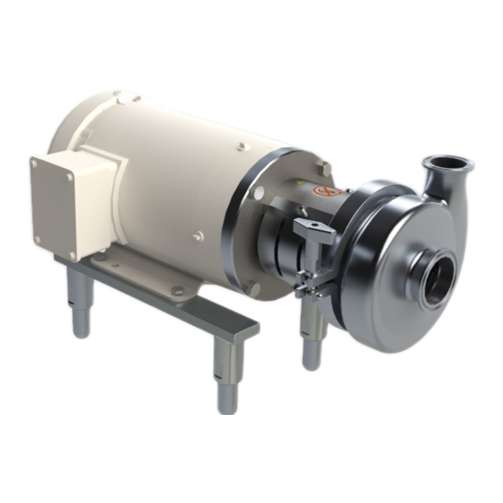
Sanitary BC/BP-Series centrifugal pumps. The Dixon Sanitary BC/BP-Series centrifugal pump is made up of two sections: the pump components (fluid end) and the motor assembly. The pump is mounted on the drive motor with an adapter and is coupled to the motor with a stainless steel stub shaft. The pump impeller on the BC-Series is mounted on the stub shaft and is secured with a floating impeller retainer pin. -
Page 5: Mechanical Specifications
Finish: sanitary polish 32RA Performance Characteristics • Nominal Capacity: up to 1200 GPM 3500 RPM • Temperature: 32°F to 212°F, consult Dixon Sanitary for other temperatures • Nominal speed: up to 3500 RPM - 60 Hz Motors and Mounting •... -
Page 6: Dimensions
7.35 3.25 7.60 284/286TC 19.00 1.50 13.13 7.00 11.00 9.50 11.16 14.63 BP6410 324/326TC 20.50 2.00 14.13 8.00 12.50 10.50 10.53 16.50 only applies to the BC/BP 328/428 ** contact Dixon Sanitary for exact measurement Instruction & Operation Manual 800.789.1718... - Page 7 1.00 210TC 7.00 1.50 5.00 13.88 1.50 250TC 10.00 1.50 5.00 18.00 1.75 280TSC 11.00 1.50 5.00 19.00 1.50 320TSC 12.00 1.50 5.00 20.50 1.50 All dimensions are approximate; for exact dimensions contact Dixon Sanitary Instruction & Operation Manual 800.789.1718...
-
Page 8: Installation
Installation Unpacking Carefully unpack all parts of the pump and inspect for damages that may have occurred during shipment. Report any damages to the carrier immediately. The ports on the pump are protected with a plastic cover. If any covers are missing or damaged, inspect the ports on the pump thoroughly for any damage. - Page 9 PUMP Installation 'D' Seal Pump Assembly ... continued from previous page Assemble back plate to adapter. a. Place the back plate assembly onto the adapter. Put even pressure down on the back plate until it is completely seated on the adapter. (see figure no.5) b.
-
Page 10: Dg' Seal Pump Assembly
Installation 'DG' Seal Pump Assembly Install the adapter onto the motor using (4) bolts and (4) lock washers. For BP441 and 641 models add adapter pins. Stub shaft alignment: a. Make sure that the key is in the motor shaft, then slide stub shaft onto motor shaft. Do not tighten set screws. -
Page 11: Bp-Series Impeller Installation
PUMP Installation BP-Series Impeller Installation D-Seal DG-Seal Replace Step 9 on page 9 with the following: Replace Step 9 on page 10 with the following: 11. Install the impeller.* 10. Install the impeller.* a. Slide the impeller onto the stub shaft. a. -
Page 12: Location
Installation Optional Leg Kit Installation and Leveling The pump can be easily leveled by installing the optional leg kit. Loosen the set screws and adjust the leg to the proper level, then tighten the set screws when level. (see the diagram at right) Scan this code on your smart phone to visit the YouTube... -
Page 13: Piping Guidelines
PUMP Installation Piping: General Guidelines PROXIMITY VOLUTE Improper piping can lead to a number of problems with pump performance which could lead to increased maintenance costs. TUBING • Ensure piping is independently supported at both the suction HANGER and discharge ports of the pump. (see the diagram at right) •... -
Page 14: Discharge
Installation Piping: Suction Guidelines ... continued from previous page • To prevent air leaks, ensure all joints in suction line are well sealed. • Use an eccentric reducer with straight side up to prevent air pockets from forming which will result in a decrease in pump efficiency. -
Page 15: Valve Location
• Verify pump rotation. An arrow sticker is supplied with every pump to show correct pump rotation. If the arrow stickers are missing, contact Dixon Sanitary for a replacement. • Correct rotation is counter clockwise when facing pump inlet connection. -
Page 16: Operation
Operation Priming the Pump To avoid damage to the pump, the pump casing must be flooded with liquid BEFORE starting the pump. Note: This is not a self priming pump. Other means must be installed to prime the pump. Fluid supply above the pump: Open supply line isolation valve. - Page 17 PUMP Operation Priming the Pump Fluid supply below the pump: Close discharge valve and open air vents. Open valve in external priming supply line. Close once liquid flows from vent valves. Close vent valves. Turn off priming supply line. Start pump. If the fluid supply is above the pump see page 16.
-
Page 18: Starting The Pump
Operation Starting the Pump Ensure pump suction is flooded using either method as explained in the previous priming section. Check for any closed valves or obstructions in the suction and discharge lines. Start the motor. Verify liquid is flowing and there is no piping connection or mechanical seal leaks. Adjust throttling valve on discharge line to desired flow. -
Page 19: Disassembly & Inspection
PUMP Maintenance Disassembly & Inspection Turn off and lock out power to pump motor. Isolate pump from system. Relieve system pressure. Remove suction and discharge lines from casing. Remove adapter guards. Loosen clamp assembly and remove. Remove casing and inspect for unusual wear or port damage. For BC-Series push back impeller and center impeller retainer in the stub shaft. -
Page 20: Seal Maintenance & Repair
Maintenance Seal Maintenance & Repair See page 19 for disassembly instructions. 'D' Seal When removing back plate inspect the stationary seal seat area for wear and/or damage. Depending upon the extent of wear, the back plate may need to be resurfaced or replaced. Remove the carbon seal, O-ring, cup and spring. -
Page 21: Troubleshooting
PUMP Troubleshooting Dixon Sanitary BC-Series pumps are manufactured and inspected to meet sanitary standards. Occasional problems may arise. The following guide will help determine the possible cause and offer suggestions on corrections to maximize the performance of your pump. In case of any electric motors issues, contact the motor manufacturer directly. If you have any questions or concerns in regards to your BC-Series pump, we encourage you to contact Dixon Sanitary. - Page 22 Material must be in contact with seal at all times. Catastrophic failure will occur. Abrasive product. Contact: Dixon Sanitary 800-789-1718 Shaft loose or bent. Readjust shaft settings, tighten shaft screws if loose. If bent, replace shaft and inspect impeller hub for uneven wear, replace impeller if worn.
-
Page 23: Model No.s & Part No.s
Specify adjustable leg kits at time of order. Leg kits will be shipped to match the frame size of motor as specified by model number. Leg kits will not be assembled. Please note, if there are options that are not listed above, please contact Dixon Sanitary (800.789.1718) for availability and pricing. -
Page 24: Part Number Key
Model No.'s & Part No.'s Part Number Key Common Parts BC114 BC216 BC218 BC328 BP441 Description Part Number Part Number Part Number Part Number Part Number Casing P1-114M P1-216M P1-218M P1-328M P1-441M Casing Enlarged Inlet P1-214M P1-516M P1-318M P1-428M P1-641M... -
Page 25: Variable Parts
PUMP Model No's & Part No's Variable Parts BC114 140TC 180TC Description Part Number Part Number Part Number Stub Shaft (BC) P6E-114-56SH P6E-114-14SH P6E-114-18SH Stub Shaft (BP) P6P-114-56SH P6P-114-14SH P6P-114-18SH Adapter P71-114-56AN P71-114-56AN P71-114-18AN P71B Adapter Bolts P71B-114B-56AB P71B-114B-56AB P71B-114B-18AB... -
Page 26: Repair Kits
1 - Impeller O-ring (P25A) * For models 114, 216 and 218/328 needing a BP repair kit, please add BP to the end of the kit part number. Model Number Buna EPDM Silicone BC114 PRK1-114B PRK1-114E PRK1-114S PRK1-114V BC216 PRK1-216B... - Page 27 1 - Outboard Gasket (P80P) 1 - Outboard Gasket (P80P) 1 - Impeller O-ring (P25A) * Model Number Elastomer Ceramic Buna PRKDG-114BCER PRKDG-114BSC PRKDG-114BTC EPDM PRKDG-114ECER PRKDG-114ESC PRKDG-114ETC BC114 SILICONE PRKDG-114SCER PRKDG-114SSC PRKDG-114STC PRKDG-114VCER PRKDG-114VSC PRKDG-114VTC Buna PRKDG-216BCER PRKDG-216BSC PRKDG-216BTC EPDM...
-
Page 28: Addendum: Older Version Adapter And Guard Assembly
Sanitary BC/BP-Series centrifugal pumps. The Dixon Sanitary BC/BP-Series centrifugal pump is made up of two sections, the pump components (fluid end) and the motor assembly. The pump is mounted on the drive motor with an adapter and is coupled to the motor with a stainless steel stub shaft. The pump impeller on the BC-Series is mounted on the stub shaft and is secured with a floating impeller retainer pin. - Page 29 PUMP (Older Version) BC-Series Installation Unpacking Carefully unpack all parts of the pump and inspect for damages that may have occurred during shipment. Report any damages to the carrier immediately. The ports on the pump are protected with a plastic cover. If any covers are missing or damaged, inspect the ports on the pump thoroughly for any damage.
- Page 30 (Older Version) BC-Series Installation 'D' Seal Pump Assembly ... continued from previous page Screw back plate pins into back plate. (see figure no.4) Position casing gasket on circumference of the back plate. Check that both the seal face on the back plate and the seal face of the carbon seal are completely clean.
- Page 31 PUMP (Older Version) BC-Series Installation 'DG' Seal Pump Assembly Install the adapter onto the motor using (4) bolts and (4) lock washers. Position the adapter such that the treaded seal flush adapter hole is located on the top. For BP441 and 641 models add adapter pins.
- Page 32 (Older Version) BC-Series Installation 'DG' Seal Pump Assembly ... continued from previous page b. While applying sufficient pressure to bring adapter and casing together put on clamp. Wing nut tightened to 25 in. lb. of torque. For BP441 & 641 models with bolted clamp, all nuts are tightened to 20 ft.
- Page 33 PUMP (Older Version) Maintenance Disassembly & Inspection Turn off and lock out power to pump motor. Isolate pump from system. Relieve system pressure. Remove suction and discharge lines from casing. Remove seal guard assembly. Loosen clamp assembly and remove. Remove casing and inspect for unusual wear or port damage. For BC-Series push back impeller and center impeller retainer in the stub shaft.
-
Page 34: Warranty
Dixon Sanitary (herein called "Dixon") warrants the products described herein, and manufactured by Dixon to be free from defects in material and workmanship for a period of one (1) year from date of shipment by Dixon under normal use and service. It's sole... - Page 35 PUMP Notes Instruction & Operation Manual 800.789.1718...
- Page 36 Dixon, founded in 1916, is a premier manufacturer and supplier of hose couplings, valves, dry-disconnects, swivels, and other fluid transfer and control products. The company’s global reach includes a wide range of products for numerous industries including petroleum exploration, refining, transportation, chemical processing, food &...
Need help?
Do you have a question about the BC114 and is the answer not in the manual?
Questions and answers