Advertisement
WARNING
Contact the original manufacturer of the vehicle to determine if this
switch is approved for your application and for mounting location.
Flaming River Industries, Inc. makes no recommendation as to mounting
location or suitability to your application. However, when installed, this
switch is a functioning part of the electrical current system. It should be
treated as battery terminals.
Terminal Covers are not furnished with this product but are recommend-
ed. Flaming River part Number FR1014TM
IMPORTANT NOTE: Please use ONLY an anodized aluminum bracket when
installing this switch.
304 Stainless Steel Fasteners
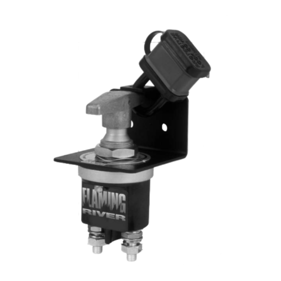
The Big Switch
Lock-Out Assembly
Part No. FR1044
Installation Instructions
"The Big Switch" is a durable,
heavy duty waterproof disconnect
switch. It is designed to complete-
ly shut off current flow from the
battery of any engine powered
vehicle or electrically-powered
accessory system. NOTE: When
installed with the mounting and
lock-out bracket supplied in this
kit and physically locked in the
"off" position with a padlock (not
included), this assembly meets
OSHA requirements for positive
"lock-out/tag-out" of power for
commercial vehicles. "The Big
Switch" is rated at 250 amps @
12V and 24V for continuous
service. (2,500 amps for 5
seconds).
Advertisement
Table of Contents

Related Manuals for Flaming River FR1044

Summary of Contents for Flaming River FR1044
- Page 1 Contact the original manufacturer of the vehicle to determine if this switch is approved for your application and for mounting location. Flaming River Industries, Inc. makes no recommendation as to mounting location or suitability to your application. However, when installed, this switch is a functioning part of the electrical current system.
- Page 2 Assembly And Installation Instructions NOTE: Before mounting the brackets, install the switch in the mounting bracket as follows: 1. Place the T-handle onto the switch stem and turn to the ON position, then remove the T-handle. 2. Remove the large hex nut and wave washer and the ON/OFF plate from the installation kit package.
- Page 3 Electrical Connection Instructions After the switch is mounted, the electrical cables can be attached to the switch. CAUTION: Disconnect the negative cable from the battery before connecting any cables to the switch. The switch will operate effectively by installing it in either the negative or the pos- itive system.
- Page 4 Figure 3 DO NOT ATTEMPT TO OVER TIGHTEN THE BASE TO THE HOUSING (7-10 FT. LBS Max..) THIS WILL VOID WARRANTY Positive or Negative Terminal Cable Cable Battery 304 Stainless Steel Fasteners Warranty Disclaimer Because of their intended usage, the manufacturer makes no warranties whatsoever expressed or implied, oral or written, to purchasers of their products regarding performance, safety, fit, merchantability or length of service.
Need help?
Do you have a question about the FR1044 and is the answer not in the manual?
Questions and answers