
Related Manuals for V-TEK Versacount II+

Summary of Contents for V-TEK Versacount II+
- Page 1 Versacount II+ Taped Component Counter User’s Guide V-TEK, Inc. 751 Summit Avenue Mankato, MN 56001 (P) 507-387-2039 www.vtekusa.com User’s Guide # 61673331...
-
Page 3: Ec Declaration Of Conformity
EC Declaration of Conformity Manufacturers Name: V-TEK Inc. Manufacturers’ Address: 751 Summit Avenue Mankato, MN 56001 USA Declare that the machinery described below complies with applicable health and safety requirements of Part 1 of Annex 1 of the Machinery Directive 2006/42/EC and EMC Directive 2004/108/EC. Confidential technical documentation has been compiled in accordance with Part A of Annex VII of Machinery Directive 2006/42/EC and is available to European national authorities on written request only. -
Page 5: Preface
Preface The Versacount II+ Taped Components Counter is built with the following features: • Accepts 7 inch and 13 inch reel diameters and carrier tape widths from 8 mm to 104 mm • SMD reel counting kit sold standard, with optional empty pocket detector •... -
Page 6: Machine Details
Machine Details Operating Temperature 0 Degrees Celsius to + 60 Degrees Celsius Although all of the components used on the machine will withstand the temperature range of 0 degrees Celsius to +60 degrees Celsius, such temperature may decrease the life of some of the components. -
Page 7: Intended Use
Intended Use The intended use of the Versacount II+ Taped Components Counter is to count taped reels of individually sealed SMD or Radial/Axial components. Use of this equipment in any other way is not recommended. Operating Environment The Versacount II+ is designed to be operated in a temperature controlled, light, industrial set- ting. -
Page 8: Safety Precautions
Please refer to Chapter 2 of this manual before performing maintenance on the machine. AC Receptacle Connect the power cord to the machine before plugging it into an outlet. Contact Information V-TEK, Inc. 751 Summit Ave Mankato, MN 56001 TEL: (507) 389-2039 website: http://www.vtekusa.com For customer service, please refer to the Customer Service Contact Sheet at the back of this manual. -
Page 9: Table Of Contents
Table of Contents EC Declaration of Conformity Preface Theory of Operation ......................i Machine Details ........................ ii Intended Use ........................iii Safety Precautions......................iv Contact Information......................iv Declaration of Conformity Chapter 1:Setup and Operation..................1 Machine Overview ......................2 Preparing the Work Area ....................5 Setup .......................... -
Page 11: Chapter 1:Setup And Operation
Chapter 1: Setup and Operation Contents Machine Overview ..........2 Preparing the Work Area . -
Page 12: Machine Overview
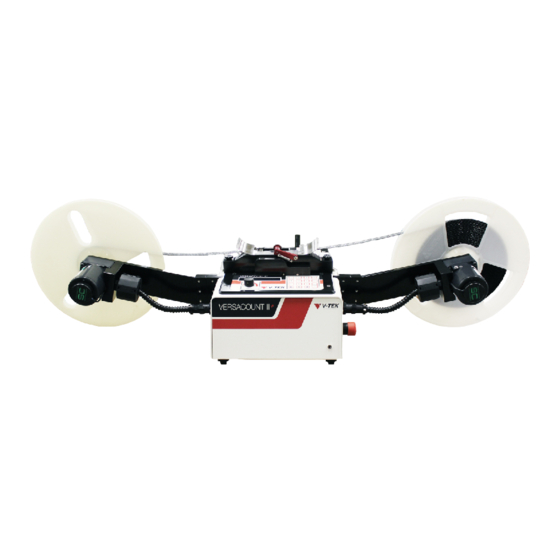
Versacount II+ User’s Guide Machine Overview Figure 1-1 A: Take-up Reel G: ESD Jack B: Empty Pocket Detector (optional) H: Emergency Stop Button C: Tape Adjuster Guide I: Motor Cable D: Reel Arm J: Take-up Motor E: Taped Carrier Reel F: Interface Panel Interface Panel Figure 1-2... - Page 13 Chapter 1: Setup and Operation Back Panel Figure 1-3 A: RS-232 Port (Serial Port) D: AC Receptacle B: Foot Switch Jack (optional) E: Fuse Holder C: EPD Jack F: Serial Plate SMD Counting Kit SMD Reel Spindles Tape Adjuster Guide Counting Head Fasteners SMD Counting Head Figure 1-4...
- Page 14 Versacount II+ User’s Guide Axial/Radial Counting Kit (optional) Axial/Radial Reel Spindles Quick Locks Tape Adjuster Guide Axial/Radial Counting Head Figure 1-5 Empty Pocket Detector Module (optional) Figure 1-6 Machine Overview 61673621.fm...
-
Page 15: Preparing The Work Area
Chapter 1: Setup and Operation Preparing the Work Area The Versacount II+ is a table-top machine which needs to be placed on a flat, stable surface in a well lit area that is a minimum of 6’ high x 7’ wide x 4‘deep (2m x 2.2m x 1.3m). When positioning the Versacount II+, choose an area that is not located below overhead gantries, walkways or power lines to ensure objects or liquids cannot be dropped on the machine from overhead. - Page 16 Versacount II+ User’s Guide When loading, unloading or running the Versacount II+ , the operator should stand in front of the machine controller to assure easy access to all controls and the Power/Emergency Stop button which is located on the right side of the machine. This position also allows the operator to view all parts of the Versacount II+ while it is in operation.
-
Page 17: Setup
Chapter 1: Setup and Operation Setup 1. Unpack the Versacount II+ Unpack the Versacount II+ from its shipping crate and place the machine onto a level and stable surface. The crate should contain: • Versacount II+ Base • Reel arms (2) •... - Page 18 Versacount II+ User’s Guide 3. Check for Proper Fusing and Voltage The AC receptacle on the rear panel of the Versacount II+ also contains the counter’s fuse holder. The fuse holder pops out below the AC plug. Two 2 amp SLO BLO 5mmx20mm fuses should be installed. Once the fuses are placed into the holder, the holder snaps back into the input module.
- Page 19 Chapter 1: Setup and Operation 6. Install the Empty Pocket Detector (optional) The empty pocket detector (EPD) is an optional module that can be purchased for use with the Versacount II+. It is used to detect and track the number of empty pock- ets in a reel of SMD carrier tape.
-
Page 20: Operating Instructions
Versacount II+ User’s Guide Operating Instructions The Versacount II+ can be used in a number of configurations depending on the options that have been purchased with the counter. This section will cover three basic configurations and out- line the general procedure the operating the Versacount II+ counter for each. The standard configuration of the Versacount II+ is counting taped SMD component reels without an empty pocket detector. -
Page 21: Initial Setup
Chapter 1: Setup and Operation Initial Setup Main Menu When the Versacount II+ is powered up, the LCD Versacount II+ Rev #35 screen displays the Main Menu shown in the fig- ure at right. <- SETUP OPTIONS -> Figure 1-10 The Main Menu screen offers two choices which can be selected by pressing the appropriate arrow key. - Page 22 Versacount II+ User’s Guide Clock Settings. 05/23/2007 03:00 PM If the CLOCK option is selected, the Clock Confir- mation screen is displayed, as shown in Figure 1- <- CHANGE OKAY -> 12. This screen allows the current date and time Figure 1-12 setting to be reviewed and changed.
- Page 23 Chapter 1: Setup and Operation Date ENTER DATE (1-31) This screen (Figure 1-16) is used to set the current day of the month by entering a number from 1 to PRESS ENTER 31. Pressing the ENT key will advance to the next screen.
-
Page 24: Counting Smd Reels Without An Epd
Versacount II+ User’s Guide Counting SMD Reels without an EPD When counting SMD reels without an EPD module, the Versacount II+ will keep a count of the number of pockets between the start and stop point on the reel. The counter will not detect when components are present or absent and cannot detect where the components on the reel begin or end. - Page 25 Chapter 1: Setup and Operation 0 and the counter will count the reel again in the other direction until the same stop count of 2000 is reached. If a change is desired, enter the stop count value while STOP is flashing and then press ENT to continue.
- Page 26 Versacount II+ User’s Guide Run Screen Press STOPGO to continue When the ENTER key is pressed while PITCH is flashing, the screen shown in Figure 1-23 will Press Enter to Go back. appear. This screen gives the operator the oppor- Figure 1-23 tunity to continue and begin counting a reel or to return to the Setup screen and review the settings...
- Page 27 Chapter 1: Setup and Operation The arrow symbol on the Run Screen indicates the direction in which the counter will count the reel. The direction can be changed by pressing either arrow key while the counter is stopped. The total count of parts is also displayed. STOP/GO=RUN indicates that the counter will begin running when STOP/GO key is pressed.
-
Page 28: Counting Smd Reels With An Epd
Versacount II+ User’s Guide Counting SMD Reels with an EPD When counting SMD reels with an EPD module installed and enabled, the Versacount II+ will keep a count of the number of pockets between the start and stop point on the reel. In addition to this, it will detect whether a part is present in each pocket, track the number of empty pockets it detects, and adjust the total count of parts accordingly. - Page 29 Chapter 1: Setup and Operation Alternatively, if the task is to confirm that exactly 2000 parts are present on the reel, the stop count should be set to 2000. Then the counter will stop after counting 2000 parts. The operator can then confirm the total count by reversing the count direction.
- Page 30 Versacount II+ User’s Guide Empty Pocket Detector Enable The EPD setting toggles the Empty Pocket Detector on and off. When the EPD is disabled, it will not detect or count empty pockets nor stop the counter at the end of a reel. Press the right or left direction arrow on the keypad to enable or disable the EPD.
- Page 31 Chapter 1: Setup and Operation Begin by centering the last empty pocket before the first part to be counted between the scribe lines on the tape guide located under the EPD sensor. The green and orange LEDs on the top of the sen- sor should be lit, indicating that the center hole in the empty pocket has been detected.
- Page 32 Versacount II+ User’s Guide Pressing the ESC key will exit the Run screen and return to the Setup screen. This will reset the count to zero (0); therefore, this should not be done unless the count is complete or being restarted.
-
Page 33: Counting Leaded Reels
Chapter 1: Setup and Operation Counting Leaded Reels When counting leaded reels, the Versacount II+ will keep a count of the number of parts that pass through the axial/radial counting head. The EPD module cannot be used with the axial/ radial counting head. - Page 34 Versacount II+ User’s Guide If a change is desired, enter the stop count value while STOP is flashing and then press ENT to continue. Pressing ENT without entering a new number will accept the current setting and con- tinue to the next setting. Count Direction The DIR setting selects in which direction the counter will run once it begins counting a reel.
- Page 35 Chapter 1: Setup and Operation If no further changes to any settings are needed, align the first part as shown in Figure 1-39. If counting the reel from left to right, position the first part in position B, to the left of the scribe mark on the tape adjuster.
- Page 36 Versacount II+ User’s Guide The counter will continue counting pockets while in the stopped condition. The operator can turn the reels manually to reach an exact count, if desired. Alternatively, pressing STOP/GO will cause the counter to resume transfering the reel, if the counter was stopped before reaching the STOP count.
-
Page 37: General Notes On Operation
Chapter 1: Setup and Operation General Notes on Operation Manual vs. Automatic Counting The Versacount II+ will keep an accurate count of parts and empty pockets regardless of whether a reel is transferred by hand or by using the Versacount II+’s take-up motors. It is usually most efficient to allow the Versacount II+ to function automatically, using the STOP/ GO key or foot switch and the speed control. -
Page 38: Hardware Option
Versacount II+ User’s Guide Hardware Option Dymo Label Writer SE450 Printer V-TEK offers a compact, high quality label printer to be used in conjunction with the Versacount II+. Printer Installation 1. Load the label paper as described in the printer manual. -
Page 39: Pc Software Option
Chapter 1: Setup and Operation PC Software Option A second option offered by V-TEK for use with the Versacount II+ is a cable and software driver that can be used to integrate the counter with a PC to receive count data from the counter. -
Page 40: Foot Switch Option
Versacount II+ User’s Guide Using the Software Option When the serial cable to the PC is installed and the software is enabled in the counter’s operator interface, a data message can be sent to the integration PC when a reel count is complete by pressing the 5 key on the number pad. -
Page 41: Maintenance Instructions
Maintenance Instructions Contents Safe Maintenance Steps ........32 Safe Maintenance Steps . -
Page 42: Safe Maintenance Steps
There are no internal parts that can be serviced by the customer/user. If any problems are encountered while using the Versacount II+, contact your V-TEK service rep- resentative, referring to the Customer Service Contact sheet located at the back of this manual. -
Page 43: Calibration
Chapter 2: Getting Started Calibration Making Calibration Reels Refer to Figure A-1 for the following information. Note: Calibration requires the Empty Pocket Detector (EPD) option, which can be purchased separately. 1. Obtain a good quality reel of any size tape that has over 600 empty pockets. 2. - Page 44 Versacount II+ User’s Guide Calibration 61683512.fm...
-
Page 45: Spare Parts List
Spare Parts List Versacount II+ Part Number Description Quantity Base Machine 101908 Filter RFI, AC input fuse holder 102012 LCD display 102354 Motor Firmware 102358 Main Firmware 103518 Power supply board 105534 Motor 105668 Speed control pack 109053 Membrane key pad (old) 109093 Membrane key pad (new) 112557... - Page 47 I S I & : ) s...
- Page 48 & : ) s...
- Page 49 & : ) s...
- Page 50 & : ) s...
- Page 51 & : ) s...
- Page 52 & : ) s...
- Page 53 & : ) s...
- Page 54 " 4 " 2 " 4 " 4 & : ) s...
- Page 55 I F I & : ) s...
- Page 56 I F I & : ) s...
- Page 57 & : ) s...
- Page 58 I S I & : ) s...
- Page 59 & : ) s...
- Page 60 & : ) s...
- Page 61 I S I & : ) s...
- Page 62 & : ) s...
- Page 63 & : ) s...
- Page 64 & : ) s...
- Page 65 I S I & : ) s...
- Page 66 . F I & : ) s...
- Page 67 " 2 & : ) s...
- Page 68 & : ) s...
- Page 69 751 Summit Avenue Mankato, MN USA 56001 Website: www.vtekusa.com Email: service@vtekusa.com Phone: (507) 387-2039 For inquiries regarding spare parts, tape and reel supplies, or the ser- vice department, please call or write: Phone: (507) 387-2039 Email: service@vtekusa.com Please provide the machine model and serial numbers with all inquiries. NOTES ____________________________________________________________ ____________________________________________________________...
- Page 70 Service and Parts Contacts 61053915.fm Page 2...
- Page 71 VERSACOUNT II+ Document List Section File Name Cover Page 1 of 1 61674219.fm EC Declaration of Conformity Page 1 of 1 Versacount DOC.doc Preface Page i-iv 61673513.fm Table of Contents Page 1 of 1 61673413.fm Chapter 1: Setup and Operation Pages 1-30 61673621.fm Chapter 2: Maintenance...
- Page 73 12. The warranty applies only to normal use of the equipment and shall be void if V-TEK determines that defects in or failures of the equipment were caused by the Customer’s negligence including the lack of proper preventative maintenance, misuse or accident or by unauthorized repair, alteration or installation.
- Page 76 751 Summit Avenue Mankato, MN 56001 (507) 387-2039 FAX: (507) 387-2257 www.vtekusa.com Email: info@vtekusa.com...
Need help?
Do you have a question about the Versacount II+ and is the answer not in the manual?
Questions and answers