Table of Contents
Advertisement
Quick Links
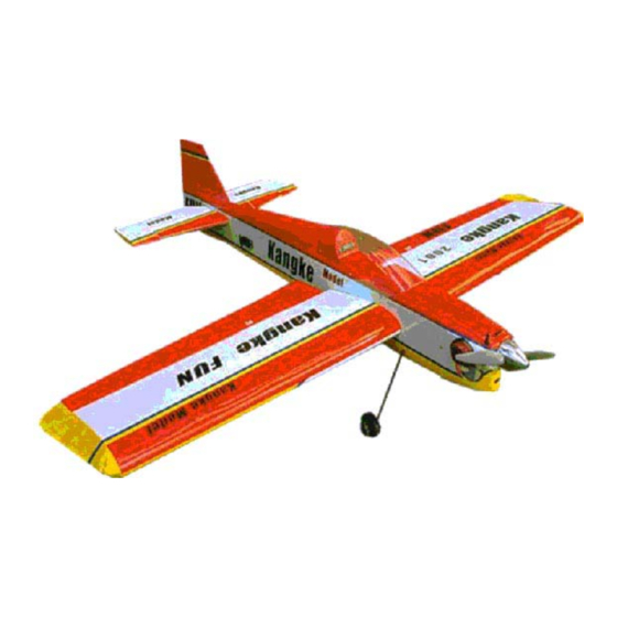
FUN-50
ARF
ASSEMBLY MANUAL
This Manuel is the sole property of Kangke Industrial USA, Inc. Reproducing any part without the
consent of Kangke Industrial USA, Inc. is a lawful violation.
Kangke Industrial USA, Inc. 65 East Jefryn Blvd. Deer Park NY 11729
http://www.kangkeusa.com
E-mail:
info@kangkeusa.com
1-877-203-2377
fax 1-631-274-3296
Warranty:
Kangke Industrial USA Inc. guarantees the kit to be free of defects in both material and workmanship at the date of
purchase. This warranty does not cover any parts damaged by use or modifications. In no case shall Kangke Industrial's liability exceed the
purchase cost of this kit. Since Kangke Industrial has no control of final assembly and material used by user for final assembly, no liability
shall be assumed or accepted for any damage resulting from the use by user of final user-assembled products. This kit has been flight test for
normal use. If the plane will be used for extremely high stress flying, the modeler is responsible for reinforcing the high stress points. Inspect
this kit immediately after receiving it, report any missing and damaged parts within 10 business days otherwise the claim may be denied.
Advertisement
Table of Contents

Related Manuals for KANGKE INDUSTRIAL FUN-50


Summary of Contents for KANGKE INDUSTRIAL FUN-50
- Page 1 This warranty does not cover any parts damaged by use or modifications. In no case shall Kangke Industrial’s liability exceed the purchase cost of this kit. Since Kangke Industrial has no control of final assembly and material used by user for final assembly, no liability shall be assumed or accepted for any damage resulting from the use by user of final user-assembled products.
-
Page 2: Hobby Items
Congratulations! Kangke Industrial USA, Inc. brings you one of the finest ARF fun-fly models available. Skilled craftsmen combined with top grade materials and precision jigs have all come together to produce an aircraft with outstanding flight qualities. If you follow the directions carefully the performance of this aircraft will surely please you. -
Page 3: Wing Assembly
WING ASSEMBLY Remove the tape from the servo wire pull string at the center of the wing. Work the string through the exit hole in the wing bottom and secure. The following steps must be done quickly before the epoxy has time to set up. Read the procedure and gather the materials before starting. -
Page 4: Fuselage Assembly
Stretch masking tape across the joint in such a way as to apply pressure to the joint. Lay the Looking through the rudder slot for the line, wing flat. DO NOT DISTURB THE WING center the stabilizer in the fuselage. Using a piece UNTILL THE EPOXY HAS FULLEY CURED. - Page 5 its alignment. Wipe the excess epoxy with a paper towel moistened with alcohol. Allow to cure before proceeding. Remove the rudder from the fin. Slide the fin into the fuselage and with a felt tip pen outline the fuselage. Remove the covering 1/8-inch down as was done with the stabilizer.
-
Page 6: Fuel Tank
Slide the fuel tank into position, wedge a piece of FUEL TANK foam in at the rear of the tank to hold it in Pass the two metal tubes through the silicone position. Allow the RTV to cure. stopper. Place the large endplate on the outside and the small endplate on the inside. - Page 7 Install the wire main landing gear with the Insert pins on the centerline of each hinge to supplied straps and screws. prevent them from sliding too far in. Install the hinges, rudder and tiller arm. Install the tail wheel bracket as shown with the With the rudder correctly aligned, remove the provided screws.
- Page 8 Insert pins in the center of the hinge, install and align the aileron, then apply one drop of thin CA to each side of the hinge. Because of the lightweight airframe, the FUN-50 was designed to use standard 40-ounce servos. Our prototype used HITEC HS-425BB with excellent results.
- Page 9 Open the elevator and rudder servo holes in the The elevator push rod is made in the same rear of the fuselage. Test fit your servos and fashion. The length for the elevator is 5 ¾-inches. install the appropriate length extension. Mount the control horn 3/16-inch in from the inside edge of the elevator.
- Page 10 Trim the canopy along the indicated lines. Install the tail wheel and collar. Carefully position the canopy of the fuselage and tape in place. Secure the canopy with the provided screws. Install the remainder of the radio gear following the manufacture instructions. Open the holes in the wing for the hold down screws.
-
Page 11: Triming Basic Flight
Although the FUN-50 will fly well in wind, wait for a nice day. At the field have a helper hold the airplane, following the radio manufactures instructions perform a range check of the radio. Do this with the motor off, start the motor and do it again. - Page 12 plane. Increase the control travel, as you become more familiar with the flight characteristics until loops take about 50 feet and knife edge can be maintained with 80% stick deflection. Final roll rate should be 300-360 degrees per second. If you have followed the procedures in this Manuel you will now be rewarded with one of the finest flying sport models available.
Need help?
Do you have a question about the FUN-50 and is the answer not in the manual?
Questions and answers