Table of Contents
Advertisement
User Guide & Instruction Manual
IntelliStation
Digital Water Mixing Valve
WARNING
!
Read this Manual BEFORE using this equipment.
Failure to read and follow all safety and use information can result
in death, serious personal injury, property damage, or damage to the
equipment. Visit PowersControls.com with any questions.
Keep this Manual for future reference.
Jr.
®
Advertisement
Table of Contents
Troubleshooting

Related Manuals for Powers IntelliStation Jr


Summary of Contents for Powers IntelliStation Jr
- Page 1 User Guide & Instruction Manual IntelliStation ® Digital Water Mixing Valve WARNING Read this Manual BEFORE using this equipment. Failure to read and follow all safety and use information can result in death, serious personal injury, property damage, or damage to the equipment.
- Page 3 WARRANTY OR ANY IMPLIED WARRANTIES, is: Within a reasonable period of time after receiving a timely and bona fide claim, Powers will at its sole option (a) repair the product, or (b) replace the product (or component) with a same or similar product. A replaced product is warranted for 90 days from the date of return shipment, or for the balance of the original Limited Warranty period, whichever is longer.
- Page 4 ANY OTHER COMPUTER NETWORK OR SYSTEM; ANY HARDWARE OR SOFTWARE NOT SUPPLIED BY POWERS; ANY DATA THAT IS INCORRECT, CORRUPT OR CORRUPTED, LOST, STOLEN OR PIRATED; ANY FAILURE TO SECURE THE INTELLISTATION JR. OR THE USER'S OR ANY OTHER COMPUTER NETWORK OR SYSTEM; ANY “CRASHING” OR TEMPORARY/ PERMANENT INOPERABILITY OF INTELLISTATION JR.
-
Page 5: Table Of Contents
Radio Frequency Warnings & Hazards ..... . . 3 IntelliStation Jr. Description & Specifications ....4 Installation . - Page 6 Attention Owners and Users Thank you for purchasing the Powers IntelliStation Jr.. This equipment will provide safe and productive ® operation as long as it is installed, set up, used, and serviced in accordance with the instructions in this Manual and is properly maintained. Owners and users of this equipment have the responsibility to make cer- tain that this equipment is used properly and safely.
-
Page 7: Safety Information
Important Safety Information Reading & Understanding the Manual • Learn how to properly and safely use WARNING the equipment BEFORE installing, set up, using, or servicing. TO AVOID DEATH, SERIOUS PERSONAL • Keep the Manual available for easy INJURY, PROPERTY access and future reference. -
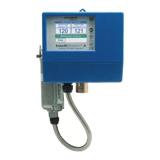
Page 8: Intellistation Jr. Description & Specifications
IntelliStation Jr. Description and Specifications The IntelliStation Jr. LFIS075VL* and LFIS100VL* are electronic water mixing valves providing user-directed control and monitoring water distribution. They include an electronic Control Module featuring a color touch screen digital display to select desired outlet water temperature, an electroni- cally actuated valve that mixes hot and cold water, a quick response temperature sensor and check valves. - Page 9 IntelliStation Jr. Description and Specifications Sensor Actuator Controller Valve Dimensions 1 5/8 3 13/16 [97 mm] 3 13/16 [97 mm] [41 mm] 6 1/2 [165 mm] Model Inlets Outlet ⁄ " ⁄ " ⁄ " ⁄ " ⁄ " "...
-
Page 10: Specifications
....................LFIS100VL 17lb (8kg) ** With Equal Pressure *** Minimum flow when IntelliStation Jr. is installed at or near hot water source recirculating tempered water with a properly sized continuously operating recirculating pump. **** Low limit cannot be less than the cold water temperature. For best operation, hot water should be at least 2°F above desired set point. -
Page 11: Installation
Installation WARNING Failure to follow all installation requirements risks possible death, personal injury, property damage, and failure of the IntelliStation Jr. LFIS075VL and LFIS100VL to ® perform as intended. • Installation of these valves MUST be performed by qualifi ed technicians, including licensed electricians and plumbers, following all manufacturer’s instructions, complying with all local, state, federal and other governmental requirements, and with all building and construction codes and standards. - Page 12 Installation Control Unit Connections 1017 Certified to 1096-01 NSF/ANSI 372 Designed and assembled in Canada Power: 115-230 V (ac) ±10%, 50/60 Hz, 20 VA Actuator Load: 24 V (dc), 0.55 A, 13 W Operating Temp: 32°F to 122°F (0°C to 50°C) E365015 Hot Water Meets FCC Part 15B, CAN ICES-3 (B)/NMB-3(B)
-
Page 13: Set Up And Programming
Set up and Programming Turn on Power 1. Turn IntelliStation Jr. power “ON” by turning on the main switch. 2. When powered up, the display will show a 70 second countdown timer and read: NOTICE The control will begin mixing operations automatically after 70 seconds. During the 70 seconds the user may adjust setting and confi gure the control by touching the PRGM menu. - Page 14 Set up and Programming Create a passcode The IntelliStation comes programmed with a factory default passcode (1017). For added security, and to help prevent unauthorized access, it is recommended that you create a unique 4 digit passcode as outlined below. 1.
- Page 15 Set up and Programming Unlock the system 1. To unlock the system, on the Unlock screen, enter your new passcode, and touch the Enter icon. NOTICE If you need to clear your entry and start again, touch the CLEAR icon. If you want to go back to Programming Menu, touch the BACK icon.
- Page 16 Set up and Programming System Setup Menu DANGER The next steps involve selecting or adjusting the mixed outlet water temperature – the hot water temperature in the water distribution system and delivered to point-of-use fixtures (faucets, sinks, tubs, showers, etc.). The owner or manager of the water distribution system is solely respon- sible for determining the safe and appropriate temperatures to protect people using, contacting...
- Page 17 Set up and Programming Note: Mixed Setback Offset is only available if a schedule is selected Selecting and Setting Outlet Water Temperature Set-point: WARNING BEFORE setting mixed outlet water temperature or electing default tempera- ture, point-of-use mixing valves and/or temperature limiting devices MUST be installed at all fixtures (faucets, sinks, tubs, showers, etc.) Set the safe, appropriate and desired outlet water temperature for your users, application and facility by...
- Page 18 Set up and Programming To set mixed setback offset (to set temperature lower during unoccupied period) press word mixed setback offset from the system setup menu and press off and ACCEPT. To set Mixed Setback Offset press On and ACCEPT. Temperature can be changed by SLIDER icon or by touching the UP or DOWN arrows.
- Page 19 Set up and Programming To change low temperature alert differential, press word low temp. alert diff. from the system setup menu. Low temperature alert differential can be changed by SLIDER icon or by UP or DOWN arrows and then pressing ACCEPT. If you are finished at this time, the system will return to a locked state if not touched for 70 seconds.
-
Page 20: Introduction
BACnet ® TP or Modbus RTU communication. The IntelliStation Jr. can be confi gured to provide remote monitoring and remote temperature set point control. BAS Connection Procedure... - Page 21 Settings in the Intellistation Control Module Menu ® When the unit powers up it displays the warning message will be shown until 70 seconds has elapsed. After 70 seconds the control will automatically redirect to the “Home” screen. The settings menu can be accessed prior to the time elapsing by touching anywhere on the screen.
- Page 22 Powers IntelliStation BAS Integration Manual From within the “Programming” menu (shown below) only the Home, Setup and UNLOCK icons are active until the control is in the unlocked state. Note: After 70 seconds of inactivity the control automatically locks and returns to the home screen.
- Page 23 Powers IntelliStation BAS Integration Manual Select the BAS icon from within the “Setup” menu to access the “Building Automation” menu shown below. The default “BAS Type” is “NONE” as shown below. To change this setting press the “BAS Type” and adjustment screen will appear (as shown below).
- Page 24 Powers IntelliStation BAS Integration Manual The Building Automation “BAS Menu” shows default settings for each of the communication protocols sup- ported by this control ( BACnet MSTP and Modbus). ® BACnet Specifi c Settings To change the BACnet Device ID, press the words BACnet Device ID, enter the device ID number, and press ACCEPT.
- Page 25 To change the BACNet baud rate, press the words Bacnet Baud Rate, select the baud rate using the UP and DOWN arrows, and press ACCEPT BACnet Protocol Implementation Statement (PICS) ® Vendor Name: Powers Vendor ID: 834 Product Name: IntelliStation Product Model Number: 109601 Application Software Version: J1267x Product Description: The IntelliStation is a mixing control designed to deliver tempered water to plumbing fi xtures.
- Page 26 Powers IntelliStation BAS Integration Manual BAS Menu BACnet Standardized Device Profile (ANNEX L) BACnet Application Specific Controller (B-ASC) Supported BIBBs (Annex K) Name DS-RP-B Data Sharing-ReadProperty-B DS-RPM-B Data Sharing-ReadPropertyMultiple-B DS-WP-B Data Sharing-WriteProperty-B DM-DDB-B Device Management-Dynamic Device Binding-B DM-DOB-B Device Management-Dynamic Object Binding-B...
- Page 27 Powers IntelliStation BAS Integration Manual BACnet Analog Parameters ® Out_ Objective_ Objective_ Present Status_ Range/ Objective_Name Description Event_State Reliability Units Identifier Type Value Flags Value Service UNITS_DE- Mixed Outlet Mixed Outlet EVENT_STATE_ GREES_ analog-Input FFF(F/T) 0 to 266F 0, 1, 4, 5...
- Page 28 Powers IntelliStation BAS Integration Manual To enter the Modbus address, press the words Modbus Address from Building Automation menu and enter Modbus address and ACCEPT. To select, press the words Modbus Data Type from Building Automation menu and enter desired data type and ACCEPT.
- Page 29 Powers IntelliStation BAS Integration Manual To enter the modbus parity, press the words Modbus Parity from Building Automation menu and select desired modbus parity by UP or DOWN and ACCEPT. Modbus Specifi cations ® Communication Protocol Modbus over RS485 Physical Layer...
- Page 30 Powers IntelliStation BAS Integration Manual Modbus Parameters ® Read= R Read/Write= R/W Analog Input Objects Parameter Red/Write Units Range Type Register Format Holding Registers Mixed Outlet Setpoint ºF 70 to 80°F Holding Input Registers Mixed Outlet Temperature ºF 0 to 266°F...
-
Page 31: Sanitization
Sanitization The Sanitization function produces high water temperatures and is intended ONLY for use as part of a user- directed, controlled and supervised thermal eradication protocol that has been safely and properly designed to help limit water-borne bacteria within the tempered water distribution system. The instructions contained in this Manual for the Sanitization function are not intended to be a thermal eradication protocol. - Page 32 Sanitization 3. Select the sanitization set point by pressing the word Temperature from Sanitization menu. 4. Using the slide bar or up and down arrows select the desired outlet water temperature. Touch the ACCEPT icon to confi rm the adjustment.
- Page 33 Sanitization 5. Next, Select the run time by touching word Time from the Sanitization menu. 6. Using the slide bar or up and down arrows select the desired run time. Touch the ACCEPT icon to confi rm the adjustment. WARNING BEFORE starting the Sanitization function, make sure you are in full compliance with a safely and properly designed thermal eradication protocol, protecting...
- Page 34 Sanitization 8. Once in the Mode menu, toggle to the ON radio button and then select ACCEPT. The Sanitization Mode is now fully functional. Note: The HOME screen will indicate you are Sanitizing the water delivery system and indicate Mixed Outlet Temperature. 9.
-
Page 35: Time Function
Time Function Touching the TIME icon on the “Programming” Menu will allow access to the Time Function: To turn on the Date & Time functionality, press the word Date & Time from the Time Options menu. Once in the Date and Time menu, toggle to the ON radio button and then select ACCEPT. To set date and time, press the word Set Date and Time from Time Options menu. - Page 36 Time Function To set date and time, select month, date, year, hour, minute and AM/PM icon at a time and change with UP or DOWN arrows then select ACCEPT. To select time format, press the word Time Format from the Time Option menu To select time format, toggle to the 12hr or 24hr radio button and select ACCEPT...
- Page 37 Time Function To select daylight savings time, press the word Daylight Savings from the Time Options menu Once in the Daylight Savings menu, toggle to On radio button and select ACCEPT.
- Page 38 Schedule Function Touching the SCHEDULE icon on the “Programming” Menu will allow access to the schedule Function: To turn on schedule, press the word Schedule from the Schedule menu Once in the schedule menu, toggle to the On radio button and then select Accept. To select the type, press the word Type from the Schedule menu.
- Page 39 Schedule Function Once in the Type menu, toggle to the Each Day radio button and then select ACCEPT. To program Each day, press the word Program Schedule from the Schedule menu. Schedule Normal and Savings time and then select ACCEPT..
- Page 40 Schedule Function If prefer all day toggle to the all day radio button and then select ACCEPT. To program All day, press the word Program Schedule from the Schedule menu. Schedule Normal & Savings time and then select ACCEPT...
-
Page 41: Wifi Function
WiFi Function Touching the Wi-Fi icon on the Programing menu will allow access to Wi-Fi screen NOTICE The Wi-Fi function should only be enabled to complete software updates. It should not otherwise be turned In the Wi-Fi menu, toggle to the On radio button and then select Accept. At this point Wi-Fi is on. - Page 42 WiFi Function Select network from the list you want to connect. Once connected, enter password ans select Connect. Once the connection is verifi ed it will say Ok.
- Page 43 Monitor Function Touching the MONITOR icon on the “Programming” Menu will allow access to the Monitor Function For mixed outlet high, press the words Mixed Outlet High from the Monitor menu then you can ACCEPT or RESET to zero For mixed outlet low, press the words Mixed Outlet Low from the Monitor menu then you can ACCEPT or RESET to zero...
-
Page 44: Monitor Function
Monitor Function To monitor actuator high reset count, press the words Actuator High Reset Count from the Monitor menu then you can ACCEPT or RESET to zero To monitor actuator low reset count, press the words Actuator Low Reset Count from the Monitor menu then you can ACCEPT or RESET to zero To select reset all. - Page 45 Toolbox Function Touching the TOOLBOX icon on the “Programming” Menu will allow access to the Toolbox Function. Scroll through the Toolbox menu using the UP and DOWN buttons to access each option. To fi nd out error code press the words Error Code from the Toolbox menu. after select Back To view the control type information for your controls press the word Firmware from the Toolbox menu and then select Back...
-
Page 46: Toolbox Function
Toolbox Function To access the history log, press words History Log fro the Toolbox menu then select Back To select load default, press the words Load Defaults from the Toolbox menu. Toggle radio button to No for no load or Yes for Load Defaults and select ACCEPT To select load temperature units, press the words Temperature Units from the Toolbox menu. - Page 47 Toolbox Function To adjust the screen brightness, press the words Screen Brightness from the Toolbox menu. Move the slider or use Up or Down arrows to adjust the brightness and select ACCEPT To clean dirty screen, press the words Clean Screen on the Toolbox menu. Toggle radio button to Yes to lock the screen to clean or No to keep it unlock and then select ACCEPT.
- Page 48 Toolbox Function To calibrate the touchscreen, press the words Calibrate Touchscreen on the Toolbox menu Press each circle to calibrate the touch screen. To reset all, press the word Reset on the Toolbox menu. Toggle the radio button to Yes or toggle to No to leave the current settings...
- Page 49 Note: Alternately, the control can be reset by opening and closing the circuit breaker switch and waiting 70 seconds to resume normal operation. Always use proper precautions when accessing circuit breaker box. 6. If problem persists after conducting the above outlined problem solving procedures, contact Powers, Technical Support at 800-669-5430 or info@PowersControls.com.
-
Page 50: Troubleshooting
Note: Alternately, the control can be reset by opening and closing the circuit breaker switch and waiting 70 seconds to resume normal operation. Always use proper precautions when accessing circuit breaker box. 6. If problem persists after conducting the above outlined problem solving procedures, contact Powers, Technical Support at 800-669-5430 or info@PowersControls.com. Problem: If screen displays "---"... -
Page 51: Error Codes
5. Waiting 1-5 minutes for the control to resume normal operation Also, ensure that there is a load (at least one tap on the mixed outlet system) present while the control is resuming normal operation. 6. If problem persists after conducting the above outlined problem solving procedures, contact Powers, Technical Support at 800-669-5430 or info@PowersControls.com. - Page 52 Scheduled Testing, Inspection and Maintenance Testing/Inspection WARNING Need for Periodic Inspection/Maintenance: This product must be tested periodically in compliance with local codes, but at least once per year or more as service conditions warrant. All products must be retested once maintenance has been performed.
-
Page 53: Scheduled Testing, Inspection And Maintenance
Scheduled Testing, Inspection and Maintenance 1. Disconnect all power and fully de-energize the IntelliStation system. 2. Once de-energized and disconnected, the display will become inactive and the control box can be opened. 3. Pop open the controller cover and then loosen two screw to expose actuator connection. As an additional safety check, once the box is open, confirm that the unit is de-energized by measuring the AC voltage across the “L”... - Page 54 Scheduled Testing, Inspection and Maintenance Valve Replacement 1. Follow actuator replacement above. 2. Remove bracket and controller from the valve 3. Un-plug sensor from the valve. 4. Remove valve and replace. Install bracket, controller and plug sensor 5. Install actuator. Using the T30 Torx driver, install the support plate T30 Torx screws (see below) until snug. Ensure that the support plate bolts are suffi ciently loose to allow for some very slight movement between the support plate and the actuator.
- Page 55 Scheduled Testing, Inspection and Maintenance 7. Tighten down the armature clamping nut using the 10mm socket and torque wrench to 50 in-lbs (5.65 N-m) 8. Using the 3/8" socket, elbow and torque wrench, torque down the support plate nut to 50 in-lbs. NOTICE Take caution not to over tighten and strip these nuts.
- Page 60 USA: Tel: (800) 669-5430 • Fax: (847) 229-0526 • PowersControls.com Canada: Tel: (905) 332-4090 • Fax: (905) 332-7068 • PowersControls.ca Latin America: (52) 81-1001-8600 • PowersControls.com IOM-P-INTELLISTATIONJR. 1818 EDP# 88006471 © 2018 Powers...
Need help?
Do you have a question about the IntelliStation Jr and is the answer not in the manual?
Questions and answers