Advertisement
Available languages
Available languages
APPLICATION
The M896 Damper Actuator is a 24 Vac motor with an
external shaft for coupling. Powered rotation is counter-
clockwise (ccw), with a maximum rotation of 110°. The
actuator is designed as a replacement actuator for the
D892 and D896 Automatic Vent Dampers or as the
original actuator on similar OEM dampers. Maximum OEM
damper operating torque cannot exceed ten in.-oz.
OPERATION
On a call for heat, the actuator automatically opens the
damper and the furnace or boiler begins its ignition cycle.
When the heating cycle ends, the burner turns off and the
actuator automatically closes the damper. Heating system
efficiency is increased because the closed damper
reduces the loss of residual appliance heat and heated
room air through the draft diverter.
INSTALLATION
When Installing this Product...
1. Read these instructions carefully. Failure to follow
them could cause a hazardous condition.
2. Check the ratings given in the instructions and on
the product to make sure the product is suitable for
your application.
3. Installer must be a trained experienced service
technician.
4. Install the M896 Damper Actuator as a replacement
only on AGA/CGA-approved damper systems.
5. After installation is complete, check out actuator
operation as provided in the Checkout section.
WARNING
Severe illness or death possible.
Prevent dangerous buildup of
carbon monoxide.
Be sure damper used with M896 has a return
spring that opens the damper if the coupler fails.
CAUTION
Electrical shock or equipment
damage possible.
1.
Disconnect power supply.
2.
Do not negate the action of any existing safety
or operational control.
3.
Make sure that the damper return spring is
operational prior to installing the actuator.
Copyright © 1997 Honeywell Inc. • All Rights Reserved
Damper Actuator
INSTALLATION INSTRUCTIONS
4.
Label all wires prior to disconnecting when
servicing controls. Wiring errors can cause
improper and dangerous operation.
To Install the M896 Damper Actuator:
1. Remove the existing actuator.
2. Make sure the damper return spring is operational.
(The damper return spring must open the damper
when the actuator coupling is removed to prevent a
dangerous buildup of carbon monoxide.)
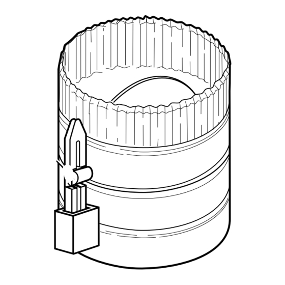
3. Locate the arrow coupler and keeper clip
(see Fig. 1).
ARROW
COUPLER
KEEPER
CLIP
A
DAMPER
SHAFT
Fig. 1. Installing arrow coupler on damper
shaft using keeper clip.
4. Slip keeper clip over arrow coupler as shown in Fig.
1. This compresses the arrow coupler.
5. Install the arrow coupler in the slot on the damper
shaft with the arrow pointing up.
6. Align the slot on the actuator shaft with the arrow
coupler and attach the actuator to the damper.
See Fig. 2. (If the actuator output shaft is not
properly aligned with the arrow coupler, manually
turn the motor knob with a screwdriver to align the
actuator shaft.)
7. Attach the actuator to the damper bracket using the
screws removed in step 1.
8. Remove the keeper clip from the arrow coupler.
9. Connect the Molex plug to the M896 Harness Cable
Connector.
X-XX UL
M896
B
M3949
69-1089B-1
Advertisement
Table of Contents

Related Manuals for Honeywell M896


Summary of Contents for Honeywell M896
- Page 1 APPLICATION servicing controls. Wiring errors can cause improper and dangerous operation. The M896 Damper Actuator is a 24 Vac motor with an external shaft for coupling. Powered rotation is counter- To Install the M896 Damper Actuator: clockwise (ccw), with a maximum rotation of 110°. The 1.
- Page 2 REMOVE PLUG ONLY IF USING VENT DAMPER. FUSE VENT BLOWS ON STARTUP WHEN PLUG IS REMOVED; DAMPER THEN MODULE OPERATES ONLY WHEN VENT M11369 DAMPER IS CONNECTED. Fig. 4. Wiring diagram for M896 (D896) connection to L8148E1166 using wiring harness with two Molex plugs. 69-1089B–1...
- Page 3 SWITCH IS MOVED TO THE SERV POSITION, THE DAMPER REMAINS OPEN. M11368 Fig. 5. Wiring diagram for M896 (D896) connection to S8600/S8610 using wiring harness with two Molex plugs. SETTINGS The service switch has both a normal (NORM ) and a NOTE: If a boiler gas control is sequenced by the service (SERV) mode.
-
Page 4: Note To Installer
4. Return the thermostat or controller to the desired does not start, leave the thermostat or controller calling for settings. heat and troubleshoot the M896/D896 as follows: NOTE TO INSTALLER: Use a voltmeter and check for 24 Vac at the S8600, Explain to the homeowner that a yearly inspec- S8610, L8148E, gas valve or other control. -
Page 5: Installation Instructions
INSTALLATION INSTRUCTIONS APPLICATION MISE EN GARDE Risque de choc électrique ou de dommage Le moteur de registre M896 est un moteur 24 V c.a. avec au matériel. arbre extérieur servant à l’accouplement. La rotation Couper l’alimentation. Ne pas empêcher le fonctionnement de tout motorisée a lieu dans le sens antihoraire sur une course... - Page 6 EST UTILISÉ. LE FUSIBLE FONDRA À LA MISE EN M896/D896 SERVICE; PAR LA SUITE, LE MODULE NE FONCTIONNERA QUE SI LE REGISTRE MF11369 D’AÉRATION EST BRANCHÉ. Fig. 4. Schéma de raccordement d’un M896 (D896) au L8148E1166 à l’aide d’un faisceau de fils et de deux prises molex. 69-1089B-1...
- Page 7 INTERRUPTEUR DE SERVICE. LA POSITION NORMALE DE CET INTERRUPTEUR EST NORM. SI L’INTERRUPTEUR EST À LA POSITION SERV, LE REGISTRE RESTE OUVERT. MF11368 Fig. 5. Schéma de raccordement d’un M896 (D896) au S8600/S8610 à l’aide d’un faisceau de fils et de deux prises molex. RÉGLAGES L’interrupteur d’entretien comporte la position normale...
-
Page 8: Dépannage
(pour provoquer une demande de chaleur) et REMARQUE À L’INTENTION DE L’INSTALLATEUR: vérifier le fonctionnement du M896/D896 comme suit : Expliquer au propriétaire qu’une inspection annuelle par un technicien d’expérience ayant Au moyen d’un voltmètre, vérifier s’il y a du courant 24 V...
Need help?
Do you have a question about the M896 and is the answer not in the manual?
Questions and answers