Table of Contents
Advertisement
Advertisement
Table of Contents

Summary of Contents for 3d-Radar Geoscope Mk4
- Page 1 GeoScope™ User’s Manual Model Geoscope Mk4 Document Version 2.0...
- Page 3 Release Notice This is the March 2013 release of the GeoScope THE WARRANTIES ABOVE STATE 3D-RADAR'S User’s Manual. It applies to the GeoScope Mk4 ENTIRE LIABILITY, AND YOUR EXCLUSIVE radar. The following limited warranties give you REMEDIES, RELATING TO PERFORMANCE OF specific legal rights.
- Page 4 Any changes or modifications not expressly approved by 3d-Radar may void the user's authority to operate the equipment. STATEMENT ACCORDING INDUSTRY CANADA Per RSS-Gen, Section 7.1.3 This device complies with Industry Canada license-exempt RSS standard(s).
-
Page 5: Table Of Contents
User’s Manual Table of Contents Table of Contents .................. 1 Abbreviations ..................1 Introduction ..................2 3d-Radar Technology ..............2 Collect up to 41 survey lines simultaneously ........3 Multi-offset recording (optional) ........... 5 Accessories/options ..............6 Hardware Components ..............8 GeoScope Unit ................ -
Page 6: Introduction
This document contains the user manual for the GeoScope™ Mk4 ground penetrating radar system, designed and manufactured by 3d-Radar AS, see http://www.3d-radar.com. The purpose of this document is to explain how to assemble the hardware and use the GeoScope software. GPR and signal processing theory is not covered by this manual. -
Page 7: Collect Up To 41 Survey Lines Simultaneously
The horizontal sampling interval determines the ∆x in the sampling grid. The array is aligned along the y-axis. The spacing between the antenna elements in the array gives the ∆y in the sampling grid. © 2013 3d-Radar AS Page 3 Revision 2.0... - Page 8 400MHz 800MHz 1200MHz Figure 4 - Wideband coverage of the 3d-Radar antenna array. The antenna elements are arranged in a linear array as shown in Figure 5 where the transmitting and receiving antennas are displaced to each other. During the survey, the radar combines the transmit/receive antennas sequentially to obtain a number of profiles (or channels) as shown in Figure ©...
-
Page 9: Multi-Offset Recording (Optional)
The Multi-offset recording allows the user to set up antenna scanning sequences with independent transmitter and receiver antenna locations. In the standard (zero-offset) antenna scanning sequence, the GeoScope transmits/receives sequentially on each antenna pair. Data is collected in the © 2013 3d-Radar AS Page 5 Revision 2.0 Date: 02/07/2013... -
Page 10: Accessories/Options
The antenna array can be equipped with a 2-wheel lightweight trailer assembly (Figure 8). The trailer connects to a standard ISO 50mm ball hitch used on cars. For railway operation 3d-Radar can provide railway wheels with adjustable track width. For high-speed surveys we recommend to mount the array directly to the vehicle Figure 8 - Typical GPR setup with a 2-wheel trailer. - Page 11 GeoScope User’s Manual © 2013 3d-Radar AS Page 7 Revision 2.0 Date: 02/07/2013...
-
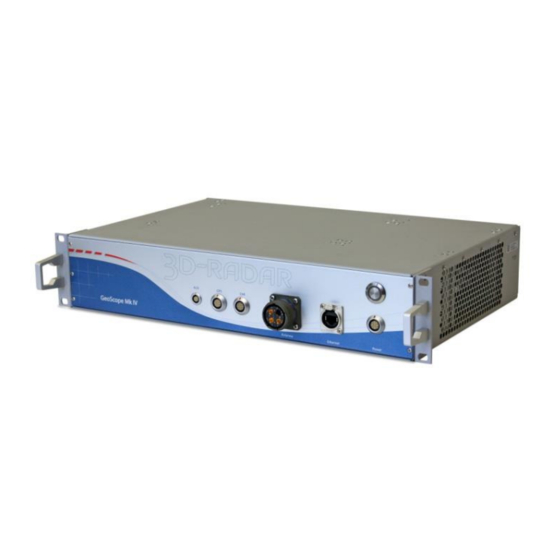
Page 12: Hardware Components
To stop the GeoScope, press the power button briefly and wait for the shutdown procedure to finishWhen the shutdown procedure is finished the power button LED goes dark and fans stop. © 2013 3d-Radar AS Page 8 Revision 2.0 Date: 02/07/2013... -
Page 13: Aux Connector
Reserved Reserved Trig out (TTL) Trig in (TTL) The Geoscope reads serial data on NMEA0183 format from any GPS or GNSS receiver. Recommended settings for the GPS NMEA output is: © 2013 3d-Radar AS Page 9 Revision 2.0 Date: 02/07/2013... -
Page 14: Distance Measurement Instrument (Dmi)
Figure 10. One tick is counted for each rising or falling edge of pulse trains A and B. Tick 8 9 10 11 12 Figure 10 - DMI pulses. The supplied DMI encoder has 1000 pulses/rev. © 2013 3d-Radar AS Page 10 Revision 2.0 Date: 02/07/2013... -
Page 15: Power Supply
A workstation grade CPU, gigabit Ethernet and a fast SSD is recommended. As of 2013-05-04, the client software runs on Java 1.6 while 3drExaminer requires Windows 7. © 2013 3d-Radar AS Page 11 Revision 2.0 Date: 02/07/2013... - Page 16 GeoScope. If you use other firewall software, and experience connection problems, please turn off this as well. An alternative to disabling the firewall completely is to enable the outgoing ports 19005 and 19003. © 2013 3d-Radar AS Page 12 Revision 2.0 Date: 02/07/2013...
-
Page 17: Antenna Array
User’s Manual 3 Antenna Array 3d-Radar AS provides different antenna array solutions for the GeoScope. Current arrays range from widths of 90 – 330 cm with number of channels ranging from 9 to 41Figure 11 shows the DX2429 antenna array which covers a width of 240 cm using 29 channels. - Page 18 Figure 13. Mount the wheel containing the DMI close to Antenna #1. Use the rigging screw to adjust the elevation. Figure 13 - Wheel bracket with DMI. © 2013 3d-Radar AS Page 14 Revision 2.0...
- Page 19 Make sure that the elevation of antenna array is sufficient to avoid that the array hits the surface during data acquisition. Recommended elevation is 10 – 50 cm above the ground surface. © 2013 3d-Radar AS Page 15 Revision 2.0 Date: 02/07/2013...
-
Page 20: Operation
There is available hard-disk space for your .3dra files which are stored on the client computer. 4. Open a web browser window and enter http://192.168.8.2 in the URL field. 5. Push the “Launch” button, and the client GUI will appear: © 2013 3d-Radar AS Page 16 Revision 2.0 Date: 02/07/2013... - Page 21 External GPS Settings are updated in the “System Settings” tab before performing a survey task. 9. 3dR Examiner software version 2.61 or newer is required for post- processing the .3dra files. © 2013 3d-Radar AS Page 17 Revision 2.0 Date: 02/07/2013...
-
Page 22: Maintenance
Never use high-pressure jet water washer on the antenna. The bottom side can be cleaned firmly with a humid rag. Do not store the antenna array inside the container if it is wet or humid. © 2013 3d-Radar AS Page 18 Revision 2.0...
Need help?
Do you have a question about the Geoscope Mk4 and is the answer not in the manual?
Questions and answers