Advertisement
Quick Links
Owner's Manual
THE GAS LOG COMPANY
ATTENTION! READ INSTRUCTIONS CAREFULLY BEFORE ASSEMBLY
INSTALLER: LEAVE THIS MANUAL WITH THE APPLIANCE ● CONSUMER: RETAIN THIS MANUAL FOR FUTURE REFERENCE
Adjustable Wrench, Pipe Wrench, Flat Head Screwdriver, Phillips Screwdriver, Pipe Sealing compound
(Only required if fittings not already prepared with pre-wrapped Teflon thread tape).
1. Air Mixer for LP Gas Burner Inlet Assembly (MA2)
2. Burner Orifice #'s 45, 49, 51,53 (01-XX)
3. Internally Tapped 3/8 Flared x 3/8 MIP Elbow (A2T)
4a. Pilot Support Bracket for F & TNA burners (PB-1)
4b. Pilot Support Bracket for CS & CXF burners (PB-2)
4c. Thermocouple Heat Shield for left side gas supply (PB-4)
1
2
3
4c
4b
8
"SE" "Remote Ready" Upgrade Kit (SE-UP1)
Kit to upgrade from "ME" to "SE" functionality. Includes: Solenoid, Receiver
and batteries. One of four Wireless Remote Transmitter Devices* is also
required (each sold separately, see below)
Latching Solenoid for Remote
Ready (STV-LS)
*Wireless Remote Transmitter Devices (each sold separately)
See instructions included with remote devices for operation.
Wireless On/Off
Wireless On/Off
Remote
Remote with
(SR-2R)
Thermostat
(THR-2R)
SPK3E - Manual " EASY" Control
General Assembly, Installation, and Operation Instructions for use with Natural Gas Burners;
F, FX, CS, CXF, TNA or Propane Gas Burners: FA, FAX, CA, CXFA, TNA/LP
REQUIRED TOOLS AND MATERIALS
4a
7
6
5
Battery Pack/Receiver
Wireless Wall
Wireless Wall
Switch
Thermostat
(WS-2R)
(TS-2R)
®
12028 E. PHILADELPHIA ST.
WHITTIER, CA 90601 U.S.A.
www.rasmussen.biz
SPK3E PARTS LIST
5. 10-32 x 3/8 bolts (qty. 3)
6. 10-32 Hex nut (qty. 3)
7. Valve Knob Extender (STV-KE2)
8. 10" flex Connector (SSCB-10)
9. Pilot-Thermocouple Assembly (J95R -NG or -LP)
10. "EASY" Safety Valve (STV-10) and Heat shield (HS-ST1)
(Green mark indicates Natural Gas,
Red indicates Propane Gas)
UPGRADE OPTIONS
Kit to upgrade from "ME" or "SE" to "RE" functionality. Includes:
DC Motor Drive, Receiver, Transmitter and batteries.
Battery Pack/Receiver
(BPR3)
(BPR3)
HI/LO DC
Motor Drive
(STV-VMD)
Variable Flame Height Remote Control Transmitter (STR-RMD)
Wireless Wall Timer
Our optional Ceramic Log House accessory (RH2) offers heat
(30/60/120 Minutes)
(WT-2R)
protection for the Battery Pack/Receiver while being pleasing
to the eye.
1
9
"RE" "Variable Flame Height" Remote Control
Upgrade Kit (RE-UP1)
Report # 10-38
REV: SPK3E-0910
Last Printed 9/17/2010
10
Advertisement

Related Manuals for Rasmussen SPK3E

Summary of Contents for Rasmussen SPK3E
- Page 1 Owner’s Manual SPK3E - Manual “ EASY” Control General Assembly, Installation, and Operation Instructions for use with Natural Gas Burners; F, FX, CS, CXF, TNA or Propane Gas Burners: FA, FAX, CA, CXFA, TNA/LP Report # 10-38 ® 12028 E. PHILADELPHIA ST.
- Page 2 ASSEMBLY STEP ONE: BURNER PAN FITTINGS (Figure 1) NOTE: If fittings do not come pre-wrapped with Teflon threaded tape, pipe compound must be applied to the non-flared threads. 1. Ensure that the BURNER PLUG (Figure 1A.) is inserted into the opposite end of the BURNER PIPE (Figure 1B) and wrench tightened.
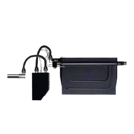
- Page 3 FIGURE 4 (CXF AND CXFA Burners FIGURE 5 (TNA / TNA-LP Burners) 10-32 bolts 10-32 nuts & bolts Pilot Thermocouple Assembly Pilot Thermocouple Assembly FIGURE 6 STEP THREE: CONNECT BURNER AND PILOT GAS SUPPLY Connect 10” FLEX CONNECTOR (Figure 6A) between the flared ends of the VALVE OUTPUT 3/8 FLARED FITTING (Figure 6B) and the BURNER INPUT 3/8 FLARED 3/8 x C) BURNER INPUT...
- Page 4 LEFT SIDE GAS SUPPLY CONNECTION Attach the Pilot Support Bracket (PB-1) to the left side of the burner pan using a 10-32 nut and bolt (Figure 7A), then place the Pilot Thermocouple Assembly over the bracket aligning the two screw holes (Figure 7b). Place the Thermocouple Heat Shield over the Thermocouple Assembly and bolt onto the Pilot Support Bracket using the supplied 10-32 nuts and bolts (Figure 7C).
- Page 5 FURTHER SAMPLES OF FIREBOX LAYOUT Each shown with “EASY” Safety Valve placed as far forward and to the side of the burner pan as possible. TNA STYLE BURNER Pilot Thermocouple Assembly Burners Flex Connector Heat Shield Burner Plug “EASY” Safety Valve Burner Pipe Internally Tapped 3/8 Flared x 3/8 MIP Elbow...
- Page 6 LIGHTING AND OPERATION STEP ONE: PILOT LIGHTING FIGURE 9 “EASY” SAFETY VALVE C) KNOB POSITION INDICATOR B) PILOT ADJUSTMENT 1. Turn VALVE KNOB (Figure 9A) to “PILOT” position. SCREW 2. Depress and hold until air is bled and gas flows to Pilot (Figure 10A).
Need help?
Do you have a question about the SPK3E and is the answer not in the manual?
Questions and answers