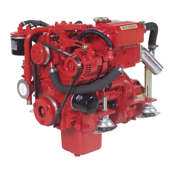
Beta Marine Beta 14 Installation Manual
Heat exchanger cooled
Hide thumbs
Also See for Beta 14:
- Operator's maintenance manual (80 pages) ,
- Installation manual (23 pages) ,
- Operator's maintenance manual (100 pages)
Table of Contents
Advertisement
Quick Links
Installation Guide &
Installation Guide &
Heat Exchanger Cooled:
Heat Exchanger Cooled:
Beta 10 to Beta 115T
Beta 10 to Beta 115T
CALIFORNIA - Proposition 65 Warning: Diesel engine exhaust and some of its constituents are known to the state of California to
cause cancer, birth defects and other reproductive harm.
Operators Manual
Operators Manual
Advertisement
Table of Contents

Subscribe to Our Youtube Channel
Related Manuals for Beta Marine Beta 14


Summary of Contents for Beta Marine Beta 14
- Page 1 Installation Guide & Installation Guide & Operators Manual Operators Manual Heat Exchanger Cooled: Heat Exchanger Cooled: Beta 10 to Beta 115T Beta 10 to Beta 115T CALIFORNIA - Proposition 65 Warning: Diesel engine exhaust and some of its constituents are known to the state of California to cause cancer, birth defects and other reproductive harm.
- Page 2 Typical Heat Exchanger Cooling System Images Are For Illustration Purposes & Not Necessarily Representative...
- Page 3 Engine Identification To ensure you receive the correct advice or parts we ask you to always provide the WOC IMPORTANT! (Works Order Card) number and/or the engine serial number. Please refer to page 4. Engine Type: Power: Speed: BETA WOC NO: Gearbox Type: Reduction Ratio: Purchased From:...
-
Page 4: Table Of Contents
Contents INTRODUCTION Engine Identification Initial Receipt of the Engine Engine Set Storage Safety Precautions Technical Specifications SECTION 1: INSTALLATION GUIDELINES Ventilation Mounting Alignment Flexible Couplings Heat Exchanger Cooling - Wet Exhaust Heat Exchanger Cooling - Seawater Inlet System Fuel System - Fuel/Water Separator, Fuel Lift Pump, Fuel Filter Fuel System - Fuel Supply &... -
Page 5: Introduction
Heat Exchanger Propulsion Engines WELCOME TO BETA MARINE Thank you for purchasing a Beta Marine Engine. We have produced this manual to provide you with important information and recommendations to ensure the most trouble free and economical operation of the engine possible. -
Page 6: Engine Identification
- To ensure you receive the correct advice or parts we ask you to always provide the WOC (Works Order Card) number and/or the engine serial number Beta Marine WOC Number The engine specification label is located on the engine rocker cover, it details the WOC number, engine type, engine The engine specification label is located on the engine rocker cover, it details the WOC number, engine type, engine serial number and output in bhp. -
Page 7: Initial Receipt Of The Engine
A full inspection of the engine must be made immediately on delivery to confirm that there is no damage. If there is any damage then write this clearly on the delivery note and inform your dealer or Beta Marine by the next working day. -
Page 8: Safety Precautions
Exhaust gases are harmful if ingested, the installer must therefore ensure that exhaust pipes are led overboard and that leakage in the vessel does not occur. J A Growcoot, C.E.O, Beta Marine Limited. D Fuel i) Fuel Lines Note: Recreational Craft... -
Page 9: Technical Specifications
Engine Technical Specifications Engine Model Beta 10 Application Recreational & Commercial Use Kubota/Beta Marine 4 - Cycle Base Engine BZ482 Cylinders - No. In-line Naturally Aspirated Turbocharged After Treatment - Exhaust Gas Recirculation Combustion Chamber - E TVCS Indirect Injection Combustion Chamber - E-CDIS Direct Injection Fuel Injection Pressure - kgf/cm²... - Page 10 Engine Model Beta 14 Application Recreational & Commercial Use Kubota/Beta Marine 4 - Cycle Base Engine BZ482 Cylinders - No. In-line Naturally Aspirated Turbocharged After Treatment - Exhaust Gas Recirculation Combustion Chamber - E TVCS Indirect Injection Combustion Chamber - E-CDIS Direct Injection Fuel Injection Pressure - kgf/cm²...
- Page 11 Beta 16 Beta 20 Beta 25 Recreational & Commercial Use Recreational & Commercial Use Recreational & Commercial Use BZ602 BD722 BD902 140 (1991) 140 (1991) 140 (1991) 21.0° 22.0° 21.0° All Speed Mechanical All Speed Mechanical All Speed Mechanical 72.0 x 73.6 (2.83 x 2.90) 67.0 x 68.0 (2.64 x 2.68) 72.0 x 73.6 (2.83 x 2.90) 24.0...
- Page 12 Engine Model Beta 30 Application Recreational & Commercial Use Kubota/Beta Marine 4 - Cycle Base Engine BD1105 Cylinders - No. In-line Naturally Aspirated Turbocharged After Treatment - Exhaust Gas Recirculation Combustion Chamber - E TVCS Indirect Injection Combustion Chamber - E-CDIS Direct Injection Fuel Injection Pressure - kgf/cm²...
- Page 13 Beta 35 Beta 38 Beta 45T Recreational & Commercial Use Recreational & Commercial Use Recreational & Commercial Use BV1505 BV1505 BV1505T 140 (1991) 140 (1991) 140 (1991) 17.0° 17.0° 18.0° All Speed Mechanical All Speed Mechanical All Speed Mechanical 78.0 x 78.4 (3.07 x 3.09) 78.0 x 78.4 (3.07 x 3.09) 78.0 x 78.4 (3.07 x 3.09) 24.0...
- Page 14 Engine Technical Specifications Engine Model Beta 43 Application Recreational & Commercial Use Kubota/Beta Marine 4 - Cycle Base Engine BV2003 Cylinders - No. In-line Naturally Aspirated Turbocharged After Treatment - Exhaust Gas Recirculation Combustion Chamber - E TVCS Indirect Injection Combustion Chamber - E-CDIS Direct Injection Fuel Injection Pressure - kgf/cm²...
- Page 15 Beta 50 Beta 60 Beta 70T Recreational & Commercial Use Recreational & Commercial Use Recreational & Commercial Use BV2003 BV2403 BV2607DI-T External 140 (1991) 140 (1991) 1st 190 (2702), 2nd 220 (3129) 16.25° 17.25° 1.25° After TDC All Speed Mechanical All Speed Mechanical All Speed Mechanical 87.0 x 92.4 (3.43 x 3.64)
- Page 16 Engine Model Beta 75 Application Recreational & Commercial Use Kubota/Beta Marine 4 - Cycle Base Engine BV3600 Cylinders - No. In-line Naturally Aspirated Turbocharged After Treatment - Exhaust Gas Recirculation Combustion Chamber - E TVCS Indirect Injection Combustion Chamber - E-CDIS Direct Injection Fuel Injection Pressure - kgf/cm²...
- Page 17 Beta 85T Beta 90 Beta 90T Recreational & Commercial Use Commercial Use Only Recreational & Commercial Use BV3307T BV3800DI BV3600T External Internal 1st 190 (2702), 2nd 230 (3271) 1st 190 (2702), 2nd 240 (3414) 140 (1991) 0.3° After TDC 14.0° 5.0°...
- Page 18 Engine Model Beta 105T Application Recreational & Commercial Use Kubota/Beta Marine 4 - Cycle Base Engine BV3800-DI-T Cylinders - No. In-line Naturally Aspirated Turbocharged After Treatment - Exhaust Gas Recirculation External Combustion Chamber - E TVCS Indirect Injection Combustion Chamber - E-CDIS Direct Injection Fuel Injection Pressure - kgf/cm²...
- Page 19 Beta 115T Commercial Use Only BV3800-DI-T External 1st 190 (2702), 2nd 240 (3414) 7.0° All Speed Mechanical 98.0 x 120.0 (3.94 x 4.72) 19.0 3769 (230.0) 115.0 @ 2800 85.7 @ 2800 348.0 @ 1600 Intake Manifold Air Heater 1-3-4-2 0.15 (0.0059) 0.5 >...
-
Page 20: Section 1: Installation Guidelines
Therefore Beta Marine can accept no responsibility for any damage or injury incurred during the installation of a Beta • Engine parts and accessories that require frequent Marine engine whilst following these guidelines. -
Page 21: Mounting
An engine will produce radiated heat - approximately Best practice for efficient and effective ventilation is an air equal to of the engine output power. Additionally, intake that is located in the engine compartment/room larger amp starter battery and/or domestic battery that is as low as possible, allowing cooler air to enter bank charging alternators create heat, building ambient below the engine an air outlet with an electric powered... - Page 22 - requires shims bearer modifications to correct ENGINE INSTALLATION AT AN ANGLE Beta Marine propulsion engines can be installed at angles To recalibrate the dipstick, first ensure all oil is drained up to a maximum of 15° flywheel up or flywheel down from the engine pre-installation and replace the oil filter, when static, and can be run at up to 25°...
-
Page 23: Alignment
ALIGNMENT To obtain accurate alignment the flexible mountings must mounted on a magnetic foot so that they are aligned be adjusted until alignment is attained, and the mountings within 0.125mm (0.005”). The propeller shaft must be must be locked in position. The engine/gearbox unit has centered in the stern tube and running true - through to be aligned with the propeller shaft in two ways. -
Page 24: Flexible Couplings
NB: If a constant velocity drive shaft is being considered Constant Velocity Drive-Shafts for fitting then it maybe necessary to have the standard engine drive plate that is supplied replaced to avoid torsional noise problems. Please contact Beta Marine for technical guidance. -
Page 25: Heat Exchanger Cooling - Wet Exhaust
ENGINES WITH HEAT EXCHANGER COOLING Heat Exchanger Cooling Sea Water Level Heat Exchanger cooling takes in sea water through the blown by the engine exhaust through a ‘gooseneck’ and bottom of the hull via a seacock with a strainer, to the out of the stern of the boat. - Page 26 HEAT EXCHANGER COOLING - WET EXHAUSTS Three major problems that can easily occur when installing exhaust hoses, or both. This can happen when the a heat exchanger engine in a vessel which need to be vessel is sailing into a big sea and a surge is set up in managed to ensure the engine is not subjected to any exhaust system as the vessel pitches - with the engine possible ‘hydraulic lock’.
- Page 27 HIGH-RISE EXHAUST If the standard injection bend is too low then Beta Marine If it is still not enough then an ‘antisyphon’/vacuum valve offer high-rise injection bends that may add either 15 cms must be fitted 50 cms above the ‘loaded’ water line sea or 20 cms to the height.
- Page 28 WATERLOCK/SILENCER Waterlock/Silencer Positioning Always fit a waterlock/silencer to stop any water in the Position of silencer in relation to exhaust hose exhaust system back filling the engine. The water lock length: should always be fitted at least 30 cms away from the Length (L) Height (H) injection bend and at least 30 cms below the injection...
-
Page 29: Heat Exchanger Cooling - Seawater Inlet System
(at the manifold flange). SEA WATER INLET FOR HEAT EXCHANGER COOLED ENGINES Beta Marine engines are fitted with a gear driven sea Seacock Inlet/Seawater water pump which sucks in seawater (raw water) to cool Engine Pump Hose I.D... - Page 30 2. Good access to the inlet sea cock from inside your 4. A normal inlet sea cock type ‘A’ is recommended as boat is essential so that debris or seaweed trapped in this can be ‘rodded out’ to remove blockages, please the intake can be removed.
- Page 31 STERN GEAR LUBRICATION IMPORTANT! - ENGINE COOLING Stern Bleed Feed If a ‘water feed take off’ is required for stern gear lubrication of the cutlass bearing or if you have an anti- syphon valve with ‘continuous bleed’, then the connection must be taken after the heat exchanger (not before) and the maximum size should be an ”...
-
Page 32: Fuel System - Fuel/Water Separator, Fuel Lift Pump, Fuel Filter
IMPORTANT! are more reliable and less likely to let air into the fuel system. Beta Marine warranty will not cover fuel • Be sure to use a strainer when filling the fuel tank. equipment when more than 7% Biodiesel is Dirt or sand in the fuel may cause trouble in the fuel used. -
Page 33: Fuel System - Fuel Supply & Leak Off
FUEL SUPPLY & LEAK OFF Fuel Supply and Leak Off Engine (All Fuel Connections Supplied) Fuel injectors Vent Fuel injection pump Flexible Fuel Fuel tank Connections to be used Fuel filter Stop tap/valve Fuel/water separator Fuel lift pump NOTES: 1. A fuel/water separator must be installed. 5. -
Page 34: Cooling - Calorifier Connections
CALORIFIER CONNECTIONS Engines can be fitted with optional calorifier connections Once connected fill the coolant level as described in so that the engine coolant circuit is allowed to flow ‘Filling The Fresh Water System’ then run the engine through a calorifier tank to heat water for domestic use. off load for 10 minutes. -
Page 35: Cooling - Engine Coolant
‘B’ - The remote header expansion tank pressure cap Remote header expansion tank kit – when ordered must always be Beta Marine, P/N 209-03066 rated @ 22 with an engine or generating set, the kit is supplied PSI. - Page 36 ENGINE COOLANT The coolant solution must be a mixture of 70 > 50% fresh water to rise to 124°C with a 13 psi pressure cap fitted. water and 30 < 50% anti-freeze. This requirement also The water temperature alarm switch will however be applies to warm and tropical climates as the solution activated at 95°C to 100°C.
- Page 37 c) Fill heat exchanger to the top of the filler neck and k) Coolant should be drained off every 2 years and replace cap. Press down firmly on filler cap and hand replaced with a new solution. tighten in a clockwise direction. NB: When draining the engine coolant system, ensure the d) Run the engine for 5 minutes on no load (out of gear), engine has cooled sufficiently to prevent scalding from hot...
-
Page 38: Batteries And Cables
BATTERY INSTALLATION Starter batteries and battery cables are a major consideration for engine starting systems. Incorrect selection of both battery and cables is a major cause of starting failure. BATTERIES 1. Battery sizes: For starter battery capacity 4. Batteries must be in good condition and must hold recommendation please refer to ‘Technical voltage. - Page 39 25mm (4 AWG) Cable Engine Cranking Amp Cable Volt drop* Max length, both cables added together Up to Beta 45T 0.00017V 4.7m Up to Beta 50 0.00017V 3.9m Up to Beta 60 0.00017V 2.8m Up to Beta 115T 210/250** 0.00017V Not suitable 35mm (2 AWG) Cable...
- Page 40 BATTERY CHARGING For efficient charging of the batteries we recommend setting the engine to a minimum of 1,200 rpm when charging out of gear until the battery/ies are fully charged. IMPORTANT This also applies for AC generation through an inverter. Charging below 1,200 rpm risks damage.
-
Page 41: Lubrication - Engine Lubrication
FILLING THE ENGINE WITH OIL For quantities of oil required please refer to pages 7 to 17. When using an oil of a different make or viscosity from the previous one, drain out the old oil. Never mix two When checking the engine oil level, do so before starting, different types of oil. -
Page 42: Bleeding The Fuel System
BLEEDING THE FUEL SYSTEM 1. Bleeding the fuel system for initial start up. CAUTION! 2. The fuel system must have all the trapped air carefully TO AVOID PERSONAL INJURY: ‘bled’ out; starting at the fuel tank and progressively working through to: the fuel/water trap, the fuel filter, •... - Page 43 Depending on engine fuel filter type follow either steps 6 & 8 or steps 7 & 8. 6. Move the hand priming lever on fuel lift pump up and 7. Move the hand priming button on the fuel filter until down (please refer to image 42) until fuel with “no fuel with “no bubbles”...
-
Page 44: Control Panels - Overview
CONTROL PANEL OVERVIEW BETA MARINE KEY SWITCH CONTROL PANELS Optional Control Panel ‘A’ 150mm Is key switch controlled for engine preheat & start, push button controlled for engine stop, has a green light indicator for ‘power on’, red warning light indicators &... - Page 45 CONTROL PANEL OVERVIEW BETA MARINE PUSH BUTTON CONTROL PANELS 180mm Optional Control Panel ‘ABVW’ Is push button controlled for engine preheat, start & stop, has a tachometer with running hour recorder, green light indicator for ‘power on’, red warning light indicators &...
- Page 46 CONTROL PANEL OVERVIEW 190mm Optional Digital Control Panel ‘D’ Our most advanced engine control/monitor module is On vessels with twin engine installations each engine water resistant to IP67. As well as controlling the engine control panel needs to be programmed as Port and ‘HEAT’, ‘START’...
-
Page 47: Control Panels - Installation
CONTROL PANEL INSTALLATION CONTROL PANELS IMPORTANT! Control modules are supplied as standard with a 3m multi-core cable for connection to the engine wiring loom. The control panel must be installed in a location Extension looms of 5m or more are available should your where the helmsman can either see or hear the installation require it or you wish to relocate your existing alarm system. -
Page 48: Section 2: Initial Generating Set Engine Start Up
Section 2: Initial Engine Start Up INITIAL ENGINE START UP IMPORTANT! CHECKS PRIOR TO INITIAL START UP Re-Check: 1. Flexible mountings and engine room ventilation. 6. Control panel installation and connection. 2. Exhaust installation. 7. Fuel system is initially bleed. 3. -
Page 49: Normal Starting And Stopping
NORMAL STARTING AND STOPPING KEY SWITCH CONTROL PANEL - FUNCTIONALITY Control Panel Options: A, ABV, B & C. 1. Turn on the battery isolating switch/es and move the 2. Turn key to ‘START’ and hold in position until the engine engine start key to the ‘RUN’... - Page 50 NORMAL STARTING AND STOPPING PUSH BUTTON CONTROL PANEL - FUNCTIONALITY These panels control the engine with three water resistant push buttons instead of a keyswitch, and is less prone to damage and corrosion from sea water spray. Control Panel Options; ABVW, BW & CW. Turn on the battery isolating switch/es.
-
Page 51: Emergency Stopping
EMERGENCY STOPPING Every propulsion engine is fitted with a back up stop lever. WARNING! To activate and stop the engine manually, simply press the stop lever highlighted in image 45 down and hold in DO NOT leave the key in the ‘OFF’ position when place until engine stops. -
Page 52: Section 3: Maintenance And Service Guidelines
Section 3: Maintenance Guidelines MAINTENANCE SCHEDULE DAILY OR EVERY 8 HOURS RUNNING AFTER 150 HOURS • Check engine oil level. • If shallow sump (option) is fitted, change engine lubricating oil and filter. • Check gearbox oil level. • Check coolant level. EVERY YEAR OR 250 HOURS IF SOONER •... -
Page 53: Maintenance Schedule
Maintenance Schedule Daily or After After Every Every Year Every Year every 8hr first first 150hrs with or 250hrs or 750hrs running 25hrs 50hrs shallow sump if sooner if sooner Check engine oil level Check gearbox oil level Check engine coolant level Check battery fluid Check belt tension and alternator bolts... - Page 54 GENERAL MAINTENANCE 1. Water entering the key switch will eventually cause 2. Check batteries for acid level and top up if required. corrosion and could result in the starter motor being For low maintenance and ‘gel’ batteries, please refer permanently energised and burning out. Spray key to the manufacturers instructions.
-
Page 55: Checking And Changing Engine Oil
CHECKING THE ENGINE OIL LEVEL When checking the engine oil level, do so before starting, When using an oil of a different make or viscosity from the previous one, drain out the old oil. Never mix two or more than five minutes after stopping. different types of oil. -
Page 56: Checking Crank Case Breather
Sump pump location: Oil filter location: Beta 14, 16, 20 & 25 Beta 14, 16, 20, 25, 30, 35, 38 & 45T Mid engine, starboard side when viewed from the Forward end, port side when viewed from the gearbox gearbox end. -
Page 57: Checking And Changing Gearbox Oil
CHECKING THE GEARBOX OIL LEVEL 1. The gearbox is fitted with a dipstick and oil filler plug, please refer to image 53. 2. Each engine is supplied with a gearbox ‘operators manual’ which specifies the type of lubricating oil to be used, the capacity and frequency of changing of the oil. -
Page 58: Fuel Filter Replacement
FUEL FILTER REPLACEMENT 1. The fuel filter is a spin on type. Remove by turning anti-clockwise when viewed face on or from below. 2. Replace the fuel filter cartridge every 750 hours or every 2 years. Please refer to image 54. 3. -
Page 59: Seawater Pump And Cooling System
Please refer to image 56. Pliers may be required. Sea water pump location: Beta 14, 16, 20 & 25 Beta 70T & 85T Forward end, starboard side when viewed from the Mid engine port side when viewed from the gearbox end. -
Page 60: Tube Stack And 'Wasting Zinc Anode
HEAT EXCHANGER TUBE STACK AND ‘WASTING ZINC ANODE’ 1. The wasting zinc anode should be checked regularly at least every six months and replaced every year or sooner, as necessary. The anode is attached to the bolt inserted in the end cap of the heat exchanger. Please refer to image 57. -
Page 61: Belt Tensioning Adjustment
ALTERNATOR BELT TENSION WARNING! Beta 10 to 45T Polyvee Drive Belt Adjuster Belt tension must only be checked with the bolt engine switched off. BATTERY CHARGING ALTERNATOR These engines are fitted as standard with with either a Polyvee (Beta 10 to Beta 45T) or an ”A” profile (Beta 43 to 115T) belt that drives both the battery charging alternator and the fresh water/engine coolant circulating pump. -
Page 62: Air Filter Inspection/Replacement
AIR FILTER All variants (excluding Beta 70T & 85T) Are fitted with a `replaceable air filter element` which should be inspected annually and replaced every 2 years or sooner if heavily clogged. If this occurs increase inspection frequency. Beta 70T & 85T These engines are fitted with an `air filter cartridge assembly` which should be inspected annually and replaced every 2 years or sooner if heavily clogged. -
Page 63: Electrical Maintenance
WINTERISING AND LAYING UP a) The engine lubricating oil and lubricating oil filter • Start the engine and run for 5 to 10 seconds until the should be changed at the end of the season rather anti-freeze is used up and can be seen coming out of than in the spring. -
Page 64: Section 4: Troubleshooting
Section 4: Trouble Shooting Beta diesels are very reliable if installed and serviced correctly, but problems can occur and the following list gives the most common ones and their solution. Problem: Engine does not start but starter motor turns over OK Possible Cause Solution No fuel:... - Page 65 Fuel suction head is too great: Fit electric fuel lift pump. Problem: Hunting at idle Possible Cause Solution Idle adjustment screw may need adjusting: Always contact Beta Marine for advice with idle adjustment. Problem: Hunting at higher speeds Possible Cause Solution Fuel supply problem:...
- Page 66 Problem: Low oil pressure warning light on when underway Possible Cause Solution Oil frothing due to high installation angle or high oil level: Always contact Beta Marine for advice. Problem: Low oil pressure warning light when engine speed reduced to tick over Possible Cause Solution Faulty switch sender: Replace.
- Page 67 Problem: Water in lubricating oil - general Possible Cause Solution Core plug pushed out due to frozen block: Dealer or service agent to check and replace. Water pump seal damaged: Dealer or service agent to check and replace. Problem: Water in lubricating oil - heat exchanger cooled Possible Cause Solution Oil goes “milky”...
- Page 68 Problem: Vibrations Possible Cause Solution Poor alignment to shaft: The alignment must be accurate even if a flexible coupling is used (please refer to ‘Alignment’ on page 31). Flexible mounts not adjusted correctly to take even weight: Check relative compression of each mount. Flexible mount rubber perished: Replace.
- Page 69 Problem: Battery quickly discharges Possible Cause Solution High load and insufficient running: Reduce load or increase charging time. Large domestic battery banks subject to high electrical loads will take a considerable time to recharge from a single alternator. Low electrolyte level: Top up.
- Page 70 If your engine was built before July 2005, contact battery bank alternator is optional for the Beta 30 and Beta Marine for the relevant electrical trouble shooting above. guide. 3.5kVA, 230v, 50Hz Travel Power alternators and inverter NB: our standard control panels are for earth return are optional for the Beta 35 and above.
- Page 71 ELECTRICAL TROUBLE SHOOTING - ALL CONTROL PANELS Before investigating any specific electrical problem, to the correct terminals for the secondary domestic always check: battery charging alternator. • The connection between the panel harness and panel • The battery connections and inspect the condition of loom.
- Page 72 Problem Possible Cause and Solution Buzzer not functioning. The buzzer will not sound for • If light is functioning but buzzer not sounding, check green ’power on’ light connection and continuity from illuminated warning light (red not green) to buzzer board. •...
- Page 73 ELECTRICAL TROUBLE SHOOTING - B, BW, C AND CW CONTROL PANELS In addition to the fault finding detailed on the previous pages, the following is specific for control panels as listed above. Problem Possible Cause and Solution Oil pressure warning light not functioning, oil pressure •...
- Page 74 ELECTRICAL TROUBLE SHOOTING - EXTENSION HARNESSES Some installations require one of the ‘panel extension Extra attention must be given to black (ground) and 11-way connectors’ to be removed to allow the cable to black/blue (tacho), also brown (switched positive to be passed through bulkheads etc.
-
Page 75: Section 5: Drawings
Section 6: Diagram Index 1. Typical Starter Motor Ratings Page 7 2. Recommended Engine Started Battery Size Page 7 3. Beta 10 to 25 HE Engine Harness (40 Amp) Page 74 4. Beta 10 to 25 HE Engine Harness (75 Amp) Page 75 5. - Page 103 ...
-
Page 120: Section 6: Emissions
4.1.2 of Annex 1 of that Directive. The person empowered to sign on behalf of Beta Marine Limited is Mr J. A. Growcoot who is the Chief Executive Officer of the company. -
Page 121: Exhaust Emission - Rcd2 Durability
Only genuine Beta Marine or Kubota approved parts must be used. This document is to be read in conjunction with our “Enhanced Kubota Based Engine Warranty”... -
Page 122: Exhaust Emission - Epa Durability
Only genuine Beta Marine or Kubota approved parts must be used, installed (and where applicable, properly set) only by our authorized mechanic. -
Page 123: Hazardous Materials Statement
All products with moving parts can be dangerous if used improperly; Always Read Instructions For Use, Carefully. Product and performance can vary from market to market, ask your dealer or Beta Marine about available product, performance and accessories in your market. -
Page 124: Section 7: Consumable Service Parts
Section 7: Consumable Service Parts Engine Model Beta 10 Fuel Filter 211-60210 Lube Oil Filter - Engine Fitted 211-63760 Lube Oil Filter - Remote Bulkhead Mounted Option 211-70510/02 Air Filter 211-08132 Sacrificial Anode 209-61840 Heat Exchanger O-Rings 2 x 212-07273 Seawater Pump Impellor Kit - Including O-Ring 207-09041-KIT 40 Amp Starter Battery Alternator PolyVee Drive Belt... - Page 125 Beta 14 Beta 16 Beta 20 211-60210 211-60210 211-60210 211-63760 211-63760 211-63760 211-70510/02 211-70510/02 211-70510/02 211-08132 211-08132 211-08132 209-61840 209-61840 209-61840 2 x 212-07273 2 x 212-07273 2 x 212-07273 207-09041-KIT 207-09041-KIT 207-09041-KIT 212-05074 212-05074 212-05074 212-05074 212-05074 212-05074 214-04124...
- Page 126 Section 7: Consumable Service Parts Engine Model Beta 43 Fuel Filter 211-60210 Lube Oil Filter - Engine Fitted 211-70510/02 Lube Oil Filter - Remote Bulkhead Mounted Option 211-70510/02 Air Filter 211-09179 Sacrificial Anode 209-61840 Heat Exchanger O-Rings 2 x 212-07273 Seawater Pump Impellor Kit - Including O-Ring 207-09042-KIT 70 Amp 12v Starter Battery Alternator V Drive Belt...
- Page 127 Beta 50 Beta 60 Beta 70T 211-60210 211-60210 211-02817 211-70510/02 211-70510/02 211-70510/02 211-70510/02 211-70510/02 211-70510/02 211-09179 211-09179 211-08134 209-61840 209-61840 209-61840 2 x 212-07273 2 x 212-07273 2 x 209-00814 207-09042-KIT 207-09042-KIT 207-10709 214-80750 214-80750 PNA* 214-92105 214-92105 PNA* 214-92105 214-92105 PNA* PNA*...
- Page 128 Engine Model Beta 105T Fuel Filter 211-02817 Lube Oil Filter - Engine Fitted 211-70510/02 Lube Oil Filter - Remote Bulkhead Mounted Option 211-70510/02 Air Filter 211-08037/E Sacrificial Anode 209-61840 Heat Exchanger O-Rings 2 x 209-00814 & 1 x 209-11054^ Seawater Pump Impellor Kit - Including O-Ring 207-10709 70 Amp 12v Starter Battery Alternator V Drive Belt PNA*...
- Page 129 Beta 115T 211-02817 211-70510/02 211-70510/02 211-08037/E 209-61840 2 x 209-00814 & 1 x 209-11054^ 207-10709 PNA* PNA* PNA* PNA* PNA* PNA* PNA* PNA* PNA* PNA* PNA* PNA* PNA* PNA* - Required Spacer. *PNA - Part No On Application Due To Variance, K WOC Number or Engine Serial No Required. Once Known Please Populate PN In Available Space For Future Reference.
-
Page 130: Section 8: Service Record
Section 8: Service Record Service Date Responsible Commissioned First 25 hours First 50 hours Every 150 hours with shallow sump Every Year/Every 250 hours if sooner Every Year/Every 750 hours if sooner... - Page 131 Service Date Responsible...
- Page 132 Beta Marine Limited, Davy Way, Waterwells, Quedgeley, Gloucester, GL2 2AD. UK. Tel: +44 (0)1452 723492 Fax: +44 (0)1452 883742 Email: sales@betamarine.co.uk Website: www.betamarine.co.uk Ref: OM 221-20031 REV 00 - 0918...
Need help?
Do you have a question about the Beta 14 and is the answer not in the manual?
Questions and answers
short pipe on cooling system perishing where to locate it