Advertisement
Quick Links
MAV 0921-13
RG 10
011907
General
ROOM SENSOR RG 10 is used together with NIBE FIGHTER
310P/360P/410P, FIGHTER 1140/1150/1240/1250/1330/
ACVM 270 as well as with NIBE EVC 13, EVC 240 and
EVP 270. This accesory also applies to NIBE FIGHTER
1120/1240 an EVP 230.
The room sensor can correct the temperature to radiators,
floor loops or fan convectors depending on the increased
indoor temperature in connection with solar incident
radiation, heating from another heat source or increased
indoor activity.
The room sensor can also quickly correct the temperature
in connection with the reconnection of disconnected po-
wer output, for example, centralised load control.
The room sensor must be positioned with care to work
correctly, see the Installation section.
KNV Energietechnik GmbH, Gahberggasse 11, 4861 Schörfling
AT
Tel: +43 (0)7662 8963-0 Fax: +43 (0)7662 8963-44 E-mail: mail@knv.at www.knv.at
NIBE Wärmetechnik AG, Winterthurerstrasse 710, CH-8247 Flurlingen
CH
Tel: (52) 647 00 30 Fax: (52) 647 00 31 E-mail: info@nibe.ch www.nibe.ch
Druzstevni zavody Drazice s.r.o, Drazice 69, CZ - 294 71 Benatky nad Jizerou
CZ
Tel: +420 326 373 801 Fax: +420 326 373 803 E-mail: nibe@nibe.cz www.nibe.cz
Mounting & Installation
NIBE Systemtechnik GmbH, Am Reiherpfahl 3, 29223 Celle
It is important that the room sensor is not disturbed by any
DE
other heat source, for example, lamps, TV or other warm
Tel: 05141/7546-0 Fax: 05141/7546-99 E-mail: info@nibe.de www.nibe.de
objects. Curtains should not block the sensor.
Install in a neutral position where the set temperature
Vølund Varmeteknik, Filial af NIBE AB, Brogårdsvej 7, 6920 Videbæk
is required. A suitable place is on a free inner wall in a
DK
Tel: 97 17 20 33 Fax: 97 17 29 33 E-mail: info@volundvt.dk www.volundvt.dk
hall approx. 1.5 m above the floor. However, the sensor
must not be prevented from measuring the correct indoor
temperature, for example, by placing in a niche, between
NIBE – Haato OY, Valimotie 27, 01510 Vantaa
FI
shelves, behind a curtain, above or close to a heat source
Puh: 09-274 697 0 Fax: 09-274 697 40 E-mail: info@haato.com www.haato.fi
or the like. Also consider any draughts from exterior doors.
Neither must the unit be affected by solar incident radia-
tion.
NIBE Energy Systems Ltd,
GB
The conduit should be sealed next to the sensor to prevent
Tel: 0845 095 1200 Fax: 0845 095 1201 E-mail: info@nibe.co.uk www.nibe.co.uk
a draught in the pipe, which could affect the sensor.
NIBE Energietechniek B.V., Postbus 2, NL-4797 ZG WILLEMSTAD (NB)
NL
Tel: 0168 477722 Fax: 0168 476998 E-mail: info@nibenl.nl www.nibenl.nl
NIBE AB, Fekjan 15F, 1394 Nesbru
NO
Tel: 22 90 66 00 Fax: 22 90 66 09 E-mail: info@nibe.se www.nibe-villavarme.no
NIBE-BIAWAR Sp. z o. o. Aleja Jana Pawła II 57, 15-703 BIAŁYSTOK
PL
Tel: 085 662 84 90 Fax: 085 662 84 14 E-mail: sekretariat@biawar.com.pl www.biawar.com.pl
NIBE AB Sweden, Box 14, Järnvägsgatan 40, SE-285 21 Markaryd
Tel: +46-(0)433-73 000 Fax: +46-(0)433-73 190 E-mail: info@nibe.se www.nibe.eu
INSTALLATION INSTRUCTIONS
RG 10
3C Broom Business Park, Bridge Way, Chesterfield S41 9QG
Setting
This room sensor measures the temperature in homes and
regulates the heat to the heating/cooling system.
If there are thermostat valves on the radiators in the same
room as the room sensor these should be fully open in
order for the room sensor to work correctly.
However, radiator valves in areas such as bedrooms, where
a slightly lower temperature is required, should be set to
the required temperature.
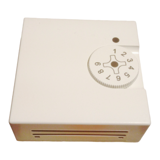
The required temperature can be set using the knob on
the room sensor unit. The scale is graduated 1 – 9, where
5 equals approximately 21 °C (house type relevant setting
of curve slope and parallel displacement). Reading the set
temperature can be done on the display screen on the ap-
paratus. However, EVC 13 does not offer this possibility.
The maximum room temperature setting is 30 °C and the
lowest setting is approximately 15 °C.*
If the room temperature changes the room sensor senses
this and compensates the flow temperature to the radia-
tors to maintain the required temperature in the room. The
reason for the lower temperature can be intensive airing
or disconnection of the power during specific periods, i.e.
centralised load control. Centralised load control is desig-
ned to save and redistribute electrical power during peri-
ods when power consumption is high and means that the
immersion heaters in heating installations do not get the
necessary power to maintain a specific room temperature.
Under normal conditions the room temperature does not
change that much.
Mechanical design
Room temperature sensor RG 10 is intended for wall
mounting. Installation can either be surface mounted or
using recessed connection boxes. The connection cable
can be either recessed or surface mounted. It should be a
screened three wire cable, where the screen is connected
to the signal ground.
The enclosure is manufactured of plastic and consists of a
bottom section with terminal blocks and components for
setting and measuring the room temperature and a knob
to set the required temperature.
The temperature sensing element is made up of an NTC-
resistor.
* 10 °C for FIGHTER 1140/1150/1240/1250/1330/ACVM
270.
GB
Advertisement

Related Manuals for Nibe RG 10


Summary of Contents for Nibe RG 10
- Page 1 NIBE Wärmetechnik AG, Winterthurerstrasse 710, CH-8247 Flurlingen centralised load control. Centralised load control is desig- Tel: (52) 647 00 30 Fax: (52) 647 00 31 E-mail: info@nibe.ch www.nibe.ch ned to save and redistribute electrical power during peri- ods when power consumption is high and means that the immersion heaters in heating installations do not get the Druzstevni zavody Drazice s.r.o, Drazice 69, CZ - 294 71 Benatky nad Jizerou...
- Page 2 The room sensor corrects the curve slope so that the flow Rumsgivare, RG 10 temperature changes. If the room temperature changes RG 10 is connected as follows. (See corresponding the room sensor senses this and lets the processor change Installation and Maintenance Instructions for terminal the flow temperature.
Need help?
Do you have a question about the RG 10 and is the answer not in the manual?
Questions and answers