Table of Contents
Advertisement
Quick Links
INSTALLATION AND MAINTENANCE INSTRUCTIONS
RTS451KEY(A) Remote Test Station
Specifications
Dimensions:
Weight:
Power Requirements
Power LED (Green):
Alarm LED (Red):
Total Current:
Alarm Response Time:
Temperature:
Humidity:
NOTICE: This manual shall be left with the owner/user of
this equipment.
NOTE: A test coil is required only for use with DH400/
DH500 models. For DH400 models order part # COIL400.
For DH500 models order part # COIL.
General Information
The System Sensor RTS451KEY(A) is an automatic fire de-
tector accessory designed to test remotely located duct and
beam detectors. For 4-wire detectors, the RTS451KEY fea-
tures a multi-colored LED that alternates between steady
green and red. Green indicates power and that the detector
board is in place. Red indicates alarm. For 2-wire detectors,
the LED will show red for alarm. Consult the detector in-
stallation instructions for additional information.
The National Fire Protection Association has published
codes, standards, and recommended practices for the in-
stallation and use of this product. It is recommended that
the installer be familiar with these requirements, with local
codes, and any special requirements of the local authority
having jurisdiction.
RTS451 Contents
1 RTS451KEY(A) remote test station
1 #4 screw for mounting bracket
1 screw pack (2 mounting screws)
2 Keys
Operation
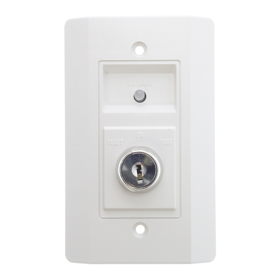
Test Function
Insert the key and turn clockwise to the "TEST" position.
Alarm Indication
With the key in the "TEST" position, some time will elapse
(40 seconds maximum) depending on the detector type, be-
fore the alarm indicating LED will turn red.
D440-03-00
4.6˝ H × 2.75˝ W × 1.8˝ D
0.22 Lbs.
14 – 35 VDC, 12 mA maximum
2.8 – 32 VDC, 7.5 mA maximum
103 mA maximum
40 seconds maximum
–10°C to 60°C (14°F to 140°F)
95% relative humidity, noncondensing
Figure 1. RTS451KEY:
Reset Function
Turn the key counterclockwise to the "RESET" position and
hold. The LED should turn off. Then, turn the key back to the
"NORMAL" position and remove. The RTS451KEY is capable
of resetting only certain models of detectors. Refer to the de-
tector installation instructions for additional information.
Wiring Instructions
Consult the appropriate detector installation instructions
for the applicable wiring diagram. The RTS451KEY mounts
to a single gang box (2
the wall or ceiling.
In Canadian applications, the RTS451KEYA is intended to
be located in the same room as the smoke detector and
within 60 feet of the unit.
1
3825 Ohio Avenue, St. Charles, Illinois 60174
1-800-SENSOR2, FAX: 630-377-6495
www.systemsensor.com
ALARM
ON
RESET
TEST
1
/
˝ minimum depth), or directly to
2
H0195-00
I56-0758-010
Advertisement
Table of Contents

Related Manuals for System Sensor RTS451KEY


Summary of Contents for System Sensor RTS451KEY
- Page 1 For DH500 models order part # COIL. General Information ALARM The System Sensor RTS451KEY(A) is an automatic fire de- tector accessory designed to test remotely located duct and beam detectors. For 4-wire detectors, the RTS451KEY fea- tures a multi-colored LED that alternates between steady...
- Page 2 Reset Reset RA – Test V Out + No Connection H0156-00 H0194-01 Figure 4. Wiring diagram for RTS451KEY to DH400ACDC duct smoke detector: DH400ACDC RTS451KEY (Red LED) Alarm Alarm Signal Aux. Power + For RTS451KEY only without a Sup. N. O.
Need help?
Do you have a question about the RTS451KEY and is the answer not in the manual?
Questions and answers