
Related Manuals for ToolPRO PLU 553024


Summary of Contents for ToolPRO PLU 553024
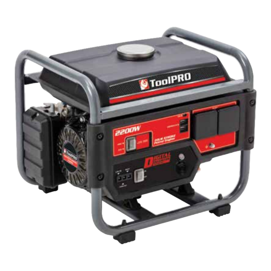
- Page 1 2200W DIGITAL INVERTER Instruction Manual PLU 553024 For service, spare parts or product information, please contact Smart Marketing Group Pty. Ltd. AUST. 1300 660 457 N.Z. 0800 474 876 03708 02/18...
-
Page 2: Table Of Contents
SUGGESTED APPLICATIONS CONTENTS These are some suggestions of appliances which could Section Page be powered by this generator. These suggestions cannot Contents be run at the same time, please read page 13 for full Suggested Applications details: Introduction • Laptop computers up to 800W Warranty •... -
Page 3: Introduction
INTRODUCTION What is covered • Manufacturing fault or defect. Dear Customer, Thank you for purchasing this generator which has How to claim under this warranty passed through our extensive quality assurance • Call customer service, phone number to the left. processes. - Page 4 COMPLETE WARRANTY STATEMENT – GENERATORS As soon as you have purchased the generator, we Damage caused by third party accessories is not recommend that you check to make sure it is intact and covered under this warranty. Damage caused to attached that you read the operating instructions carefully before equipment or third party accessories will not be covered using it.
-
Page 5: General Safety Instructions
LUBRICATION OF ENGINE PROTECT POWER LEADS FROM DAMAGE Your engine comes with NO oil in the sump. You will need Always disconnect power cords from a power supply to add engine oil, refer to pages 8 and 10 for complete socket by pulling the plug. - Page 6 EXTENSION CORDS & REELS Inspect extension cords periodically and replace if Ear Protection damaged. Never use damaged extension cord as these The use of ear protection is highly recommended when may cause injury. Always unwind any extension cords using generators. The continual noise may damage your fully before plugging into mains power supply.
-
Page 7: Specific Safety Instructions
SPECIFIC SAFETY INSTRUCTIONS • Your generator is factory set, NEVER attempt to speed Warning! Do not use the generator in areas where there is it up as this could endanger the user and damage the a risk of explosion or fire from combustible materials. The generator and/or attached appliances. -
Page 8: Electrical Information
IMPORTANT ELECTRICAL DATA This generator is fitted with a sealed electrical connection socket that is compatible with the generator. If the electrical connection socket becomes damaged it must be replaced with a complete assembly that is identical to the original, and this must be replaced by an authorised service agent. Never connect to an external power supply. -
Page 9: Components & Controls
PIC. 1 COMPONENTS & CONTROLS (PIC.1) 4. Earth bolt point for earth lead 5. 5V USB socket 1. Engine switch 6. AC socket 2. Low oil alarm indicator (Red) 7. Air filter connection screws A. It will start flashing when the engine starts with 8. -
Page 10: Operating Instructions
OPERATING INSTRUCTIONS PIC. 2 UNPACKING Carefully unpack your generator. This generator is heavy (12.8kg) and may require two (2) people to lift. Dispose of all packing material in an environmentally responsible manner. Open carton, gently lift the generator clear of the carton and packaging, this may require 2 people. - Page 11 GENERATOR ‘EARTHING’ PIC. 6 Always ensure that this generator is “Earthed” BEFORE starting and using. 1. Ensure that engine is OFF when fitting the “Earth” stake and wire. 2. Attach the wire to the “Earth” point on the generator, see Pic. 5. 3.
- Page 12 7. Slowly turn choke to OPEN / RUN by sliding the PIC. 10 choke lever to the right, Pic. 10. 8. Check that the only illuminated light is the green output power light. The generator will be running and ready for use. WARNING! Before connecting any electrical load to the generator ensure that the load does not exceed the START...
- Page 13 USING YOUR GENERATOR PIC. 13 AC OUTLET Your generator is equipped with a 240V AC power socket. This will run a range of devices providing they are with in the limits of the generators output. NOTE: The peak (surge) power requirements of some devices e.g.
- Page 14 OUTPUT INDICATOR LIGHT 4. Push the circuit breaker back in, it should stay in. If not the circuit breaker is still over heated, allow to Output indicator light (green) will remain ON during cool down for another 2 minutes before trying again operation.
- Page 15 STORAGE PIC. 14 If the generator is not to be used or is to be stored for more than one month the following storage procedure should be carried out. Drain all the fuel from the fuel tank (refer to page 18) and the carburettor (see below), ensure that all the fuel has been drained.
-
Page 16: Maintenance Chart
MAINTENANCE CHART Item Remark Pre-operation Initial 1 month or Every 3 month Every 6 month Every 12 month check (daily) 20 hours or 50 hours or 100 hours or 300 hours Check condition Spark plug Adjust gap and clean Replace if required Check oil level Engine oil Replace... -
Page 17: Maintenance
MAINTENANCE PIC. 15 CHECKING/CLEANING THE AIR FILTER For proper performance and long life, keep air filters clean. 1. Using a screwdriver unscrew the two air filter connection screws located at the top and bottom of the air filter cover. Remove the cover and set aside (Pic. - Page 18 CLEANING THE FUEL VALVE FILTER PIC. 19 The fuel valve filter prevents dirt and water that may have gotten into the fuel tank from entering the carburetor. If the engine has not been run for a long time, the fuel valve filter should be cleaned before use.
-
Page 19: Fault Chart
FAULT CHART ACTION Fill sump with No oil/ Low oil level correct oil, See page 8 Loose spark plug Tighten plug Insufficient Loose cylinder Tighten bolt compression head bolt Damaged gasket Replace gasket FUEL SYSTEM PROBLEMS Insufficient pulling Pull rope sharply speed for starting rope Foreign matter in... - Page 20 FAULT CHART CONTINUED ACTION Tripped circuit breaker Reset Check and repair Poor connection or faulty lead Indicator light ON. No AC output Broken recepticle Faulty circuit breaker Check and repair Indicator light OFF. Generator problem No AC output Output power too Engine RPM set too No load speed set high or low...
-
Page 21: Service Log
SERVICE LOG This service is to be completed within 50 hours This service is to be completed within 100 hours or 3 months of purchase, which ever comes first. or 6 months of purchase, which ever comes first. Replace Check & Adjust Replace Check &... -
Page 22: Specification
SPECIFICATIONS Inverter generator.............. TP2200DGOF Engine type..........Single cylinder, 4 stroke 135cc Engine speed..............3000-4000 r/min Oil tank capacity................500 mL Oil type......4 stroke motor oil, SAE 30W or SAE 15W-40 Fuel tank capacity.................7L Fuel type..........Unleaded 91 Petrol - no ethanol Spark plug..................F7RTC Rated voltage.............. - Page 24 2200W DIGITAL INVERTER 7L Fuel tank Recoil starter Twin USB outlet 240V AC~50Hz Outlet socket Output LED Light 12V DC Cigarette lighter socket Generator ON/OFF switch Manufactured and packaged for SRGS PTY LTD ABN 23 113 230 050 751 Gympie Road, Lawnton, Queensland 4501, Australia...
Need help?
Do you have a question about the PLU 553024 and is the answer not in the manual?
Questions and answers