Table of Contents
Advertisement
Quick Links
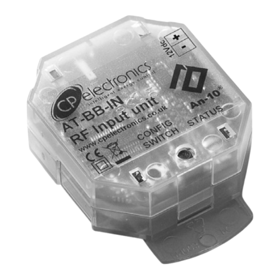
AT -BB -IN
RF input unit
Front features
Back features
Product Guide
The AT -BB -IN Input Unit provides a control interface
between a lighting system and external devices such as:
Button/switch plates
Security systems
AV equipment
The unit features seven Volt- free switch inputs that can be
activated by the contact closure of push-buttons, switches,
or relays.
Activating an input causes the unit to transmit a RF control
message to other devices, triggering various actions such
as recalling a scene, raising/lowering light levels, turning
override on/off, starting and stopping sequences, etc.
The integral RF transceiver allows wireless communication
with other An -10
fully programmable using an infrared handset (e.g. the
UHS4 or UNLCDHS) or PC control software.
The unit is powered either by the internal battery or via an
external 12Vdc supply.
Infrared Receiver (IR)
Allows the unit to receive programming commands from an
IR Handset (e.g. the UHS4) when IR Receive mode is
activated (see Config Button and Status LEDs below).
Config Button
Press this to put the unit into IR Receive mode, enabling it
to receive programming commands from an IR Handset.
Status LEDs
These flash R ed and/or G reen to indicate the following:
IR Receive mode active
Valid setting received
Invalid setting received
Software reset received
Factory reset received
Battery (type CR2477)
Provides power to the unit if an external supply is not used.
Optional 12Vdc Supply Terminal
To power the unit from an external supply, connect the
supply to this terminal ensuring correct polarity. Refer to
Technical Data on page 8 for power supply specification.
Plug -in RJ45 lead and socket
A short 8 core flat cable with plug that is supplied with each
unit, used to connect the inputs to external devices.
®
compatible products. All functionality is
at 1 second intervals
Overview
Features
Advertisement
Table of Contents

Related Manuals for CP Electronics AT-BB-IN

Summary of Contents for CP Electronics AT-BB-IN
- Page 1 Product Guide AT -BB -IN RF input unit Overview The AT -BB -IN Input Unit provides a control interface between a lighting system and external devices such as: Button/switch plates Security systems AV equipment The unit features seven Volt- free switch inputs that can be activated by the contact closure of push-buttons, switches, or relays.
-
Page 2: Installation
Installation The AT-BB-IN Input Unit can either be mounted to any Mounting bracket location suitable solid surface or concealed inside a backbox. for surface mounting. Surface Mounting Method Fit the two snap-on mounting brackets on the back side of the unit as shown in opposite. -
Page 3: Wiring Examples
Wiring examples Example 1: Using individual push-buttons RJ45 Lead 1 - Input 1 Brown 2 - Input 2 • • 3 - Input 3 Yellow • 4 - Input 4 Green • 5 - Input 5 • 6-lnput6 Black • 7 - Input 7 Orange 8- Common Grey... -
Page 4: Basic Programming
Basic programming The functionality of the AT-BB-IN Input Unit is controlled For most basic programming operations the UHS4 handset by a number of parameters which can be changed or is recommended and the following procedures are based programmed by any of the following devices: on using this device. - Page 5 Basic programming Step 3: Choose a preset configuration To simplify the programming of commonly used HINT: Where scene numbers or channel numbers are given in a Preset Configuration, these can be changed applications, a number of Preset Configurations are (after applying the Preset) by using the Map Scene/ available.
-
Page 6: Advanced Programming
Latching mode, therefore, gives rise to two possible events: The table below and on page 7 gives a summary of all • Pressed (switch closed) programmable parameters for the AT-BB-IN Input Unit. • Released (switch open) Parameter Name Default Value... - Page 7 Advanced programming Parameter Name Default Value Range / Options Description Programming Devices UHS4 UNLCDHS Control Function = Scene Select * Local On Scene 1 to 20 A Scene Select message comprises of three Local Scenes (On, Step 1 second 0 to 255* Fade Rate and off) and three Area Scenes (On, Step and off)
-
Page 8: Replacing The Battery
Directive 1999/5/EC. The declaration of conformity Material (casing) Flame retardant polycarbonate may be obtained for CP Electronics Ltd Brent Crescent, London, NW10 7XR, UK. Part numbers EBDSPIR -AT -PRM RF Ceiling PIR presence detector –...
Need help?
Do you have a question about the AT-BB-IN and is the answer not in the manual?
Questions and answers