
Related Manuals for Field Scout TDR 350


Summary of Contents for Field Scout TDR 350
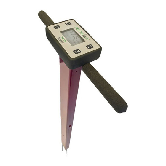
- Page 1 TDR 350 Soil Moisture Meter PRODUCT MANUAL Item # 6435 Distributed & Supported By: www.edaphic.com.au info@edaphic.com.au Ph: 1300 430 928...
-
Page 2: Table Of Contents
Appendix 2: Checking VWC Readings Appendix 3: FAQ Appendix 4: Time Zone Corrections This manual will familiarize you with the features and operation of your new Field Scout TDR 350 Soil Moisture Meter. Please read this manual thoroughly before using your instrument. - Page 3 The user can quickly transition between taking VWC readings in standard and high-clay mode. The TDR 350's shaft-mounted probe allows the user to take measurements while standing. The meter’s built-in data logger can record data from several sites and elimi- nates the need to record data manually.
-
Page 4: Shaft Dimensions
Shaft dimensions The following are the dimensions of a fully extended shaft. It is possible to reduce the length of the meter to 23” (58.5 cm) by adjusting the lower half of the shaft. 14" 5" 19.5" 38" 2.4"... -
Page 5: Specifications
Specifications Measurement Percent volumetric water content (VWC) Units Period (raw sensor reading) Resolution VWC: 0.1% VWC units EC: 0.01 mS/cm Temperature: 0.2 ˚F (0.1 ˚C) Accuracy VWC: ±3.0% volumetric water content with electrical conductivity < 2 mS/cm EC: ± 0.1 mS/cm Temperature: ±... -
Page 6: Batteries
STEPS: 1. Turn the TDR 350 upside down and remove the 4 screws. Open the bottom and separate the display module from the base plate. This may require pulling the cable slightly out of the shaft. - Page 7 Battery life The battery level is checked every time the display unit is turned on. If the battery level is low, or if a battery is inserted incorrectly, this low battery im- age shows on the full screen for about 10 seconds and then the display will automatically turn off.
-
Page 8: Button Functions
Button Functions Basic Button Operations ON/OFF or BACK button Press this button briefly to turn on the display. The meter will then display the Data screen (p. 11). To turn the meter off, press and hold this button for about 2 seconds. When in the Settings Menu screen (p. - Page 9 DELETE or UP button When on the Data screen (p. 11), press this button to delete the last measured data point from the computed Average and decrement the Count. When on the Settings Menu screen (p. 12), press this button to scroll up to the previous menu item. READ or DOWN button When on the Data screen, press and release this button to take a sensor...
-
Page 10: Display Screens
Display Screens The TDR 350 has 3 main display screens; - Startup Information screen - Data screen - Settings Menu screen Startup Information screen The Startup Information screen is displayed for about 2 seconds after the display is turned on. - Page 11 Data screen Readings from the sensor are displayed on the Data screen. The battery level in- dicator appears in the upper right corner. The run- ning average and number of readings included in that average are shown in the lower right corner. Pressing and holding the READ button will clear the average and re-set the counter to 0.
- Page 12 Settings Menu screen The contents of the Settings Menu are shown on the following figure. Use the arrow buttons to scroll to the desired option. The options are de- scribed below. For most options, pressing the Se- lect button simply toggles you through the differ- ent choices for that option.
- Page 13 Temp Source: Choose Soil Sensor or IR Sensor (IR sensor accessory will be available soon). Temp Units: Choose Fahrenheit or Celsius. Moisture Type: Choose volumetric water content (VWC%), raw sensor reading (Period), or TDR 300 mode. The latter will report a VWC that matches the output of the TDR 300 meter (no EC optimization).
-
Page 14: Meter Calibration
Meter Calibration The meter has internal calibrations for standard and high-clay soil types. It also has the option of outputting a value that matches its predecessor, the TDR 300. These calibrations will work for a large number of soils. However, each meter will have a small difference in how it responds to identical soil conditions. -
Page 15: Updating Firmware
(Appendix 1, p. 28) where a unique calibration curve is generated. Updating Firmware The firmware of the TDR 350 can be updated us- ing a USB flash drive. Firmware update files can be found at the Spectrum website. -
Page 16: Electrical Conductivity
Electrical Conductivity Electrical Conductivity Knowledge of the salinity level of your soil is an im- portant component of irrigation and nutrient management. The source of the salts in the soil ranges from the original parent material to additions from natural sources and man- agement activity. - Page 17 The TDR 350 uses the same metal rods used for soil mois- ture sensor as the electrodes for the EC circuit. The value measured is an average for the entire depth sampled. Salinity Index The TDR 350 measures the bulk EC of soil that may or may not be saturated.
-
Page 18: Meter Operation
Configuration is done in the Settings menu (pp. 12 - 13). The TDR 350 can be set to one of two Soil Type modes, Standard or High Clay. The Standard mode will be appro- priate for most mineral soils. The High Clay mode will be more accurate for soils with higher clay contents (>... - Page 19 To geo-reference data, enable the GPS capability. If you are using the FieldScout Mobile app (p. 22), Bluetooth functionality must be enabled. If GPS is disabled, the app will use the phone's GPS instead. Display Figure 2 shows a sample data screen.
- Page 20 Pilot Hole maker (item 6430PH) to make 3” holes to aid in starting the insertion of the probe rods. Press the READ button to initiate the measurement se- quence. The reading should appear almost instantaneous- ly. If the display does not detect the sensor, it will display dashes.
-
Page 21: Replacing Or Re-Attaching The Probe Block
(item 6435S). Remove the rods before separat- ing the old sensor. 1. Turn the TDR 350 upside down and remove the 4 screws. Open the bottom and separate the display module from the base plate (fig. 1). This may re- quire pulling the cable slightly out of the shaft. -
Page 22: Field Scout Mobile App/Specconnect
(Fig. 1). In freeform mode, a color-coded pushpin icon is placed at every sampling point. If the TDR 350 has a good GPS fix (p. 11), the app will use the coordinates from the meter. If not, or if the meter's GPS is disabled, it will use the inter- nal GPS of the smartphone. - Page 23 The data from the Pro version of the app is sent instantaneously to SpecConnect. Data can be viewed in map form (fig. 3), exported to an Excel spreadsheet, or viewed as a Trend Report (fig. 4). More details are available in the user's guide for the app.
-
Page 24: Data Logs
Data Logs Figure 1: Sample TDR 350 data file Downloading Data Data stored in the meter's internal memory can be transferred to your PC with a USB flash drive. Connect the flash drive to the USB port on the front of the meter. Press the Menu/Select button (p. - Page 25 Managing Data The data is stored in comma-delimited text files. The file name will match the serial number of your meter. These files can be opened with text-editing software or spreadsheet software (fig. 1). The data is separated into 11 fields. Column Description Date and time...
-
Page 26: Vwc Measurements
VWC Measurements Volumetric Water Content (VWC) The soil can be thought of as being composed of soil, water and air. The volumetric water content (VWC) is the ratio of the volume of water in a given volume of soil to the total soil volume. -
Page 27: Gps
Electronics in the TDR 350 generate and sense the return of a high energy signal that travels down and back, through the soil, along the waveguide composed of the two replaceable, stainless steel rods. The sampling volume is an elliptical cylinder that extends approximately 3 cm out from the rods. -
Page 28: Appendix 1 Soil-Specific Calibration
Appendix 1 Soil-Specific Calibration For maximum accuracy, you may choose to perform a soil-specific calibration rather than use either of the internal (Standard or High Clay) soil calibrations coded into the TDR 350’s firmware. In these cases, an independent soil moisture content measurement is re- quired. - Page 29 The final step is to plot the calculated the measured period values with the readings obtained from Field Scout TDR meter. Regression analysis can then be performed on this data to develop an equation to convert from period to...
-
Page 30: Appendix 2: Checking Vwc Readings
Appendix 2 Checking VWC Readings There are two tests that can be performed to check if the meter is operat- ing properly. Test 1 (No rods): Disconnect the rods from the probe block. Select the Period option for Moisture Type (p. 13). With no rods connected, the meter should read 1930 ±... -
Page 31: Appendix 3: Faq
Appendix 3 1. What are the factory default settings? Rod Length Turf Moisture Soil Type EC units Standard mS/cm Backlight, GPS, Auto-Off Disabled 15 minutes Bluetooth Time Zone Sound Temperature Fahrenheit 2. What type of sensor is used to measure surface tem- perature? The sensor on the underside of the probe block is a ther- mistor. -
Page 32: Appendix 4 Time Zone Corrections
Appendix 4 Time zone corrections Time Zone City Correction Wellington Honolulu Anchorage San Francisco, Los Angeles, Vancouver Phoenix, Denver, Edmonton Guatemala City, Houston, New Orle- ans, Chicago, Mexico City, Winnipeg Atlanta, Indianapolis, New York, Otta- wa, Bogota, Montreal, Toronto Asuncion Rio de Janeiro, Montevideo Sao Paulo Azores... - Page 33 Time Zone City Correction Hanoi, Jakarta Beijing, Hong Kong, Manila, Singa- pore, Taipei Seoul, Tokyo Vladivostok, Brisbane Adelaide, Melbourne, Sydney Aukland...
- Page 35 Warranty This product is warranted to be free from defects in material or workmanship for one year from the date of purchase. During the warranty period Spectrum will, at its option, either repair or replace products that prove to be defective. This warranty does not cover damage due to improper installation or use, lightning, negligence, accident, or unauthorized modifications, or to incidental or consequential damages beyond the Spectrum prod-...
- Page 36 DECLARATION OF CONFORMITY Spectrum Technologies, Inc. 3600 Thayer Ct. Aurora, IL 60504 USA Model Numbers: 6435 Description: Portable Soil Moisture\Conductivity\Temperature Probe Type: Electrical Equipment for Measurement, Control, and Laboratory Directive: 2004/30/EU Standards: EN 61326-2:2012 EN 61000-6-1:2007 EN 61000-6-3:2007+A1:2010 ICES-003:2016; ITE Emissions for Canada (ANSI C63.4:2014) FCC Part 15:2016: Emissions for Unintentional Radiators for USA (ANSI C63.4:2014) EN 55032:2015...
Need help?
Do you have a question about the TDR 350 and is the answer not in the manual?
Questions and answers